After over a hundred years of research and development, geomechanics modeling is not just a nice-to-have accessory in a drilling campaign, but it is one of the main pillars to minimize non-productive time and ensure safety throughout the entire operation. The geomechanical model integrates the magnitude and orientation of the in-situ stresses, pore pressure, and the properties that define rock strength. Without it, operational decisions rely on assumptions instead of physics.
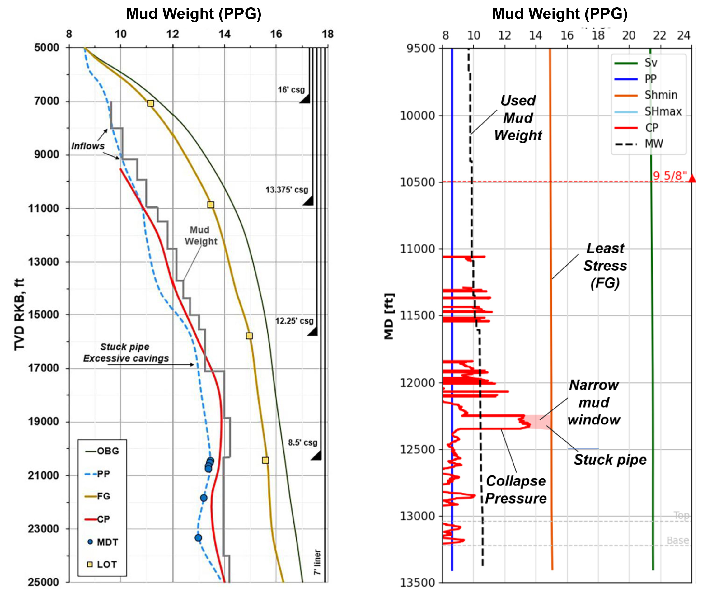
One of its most critical applications is the definition of the safe mud window. The low side of the mud window at a given depth is defined by the highest of the collapse or pore pressure. Lower mud weight results in wellbore instability or inflows. The upper bound is defined by the fracture gradient which defines the pressure at which the mud is lost to the formation through an induced fracture.
Whether the wellbore becomes unstable and develops excessive borehole breakouts depends on the relative magnitude of the near-wellbore stresses with respect to the rock strength. As the stress concentration around the borehole is dictated by wellbore orientation, a geomechanical assessment can identify safer trajectories and casing points in the early planning phases.
High pressure high temperature (HPHT) or deepwater wells are unforgiving, and are typically characterised by narrow mud windows, where the difference between the upper and lower bound can be under 1 ppg. In this situation, any operational fluctuations of bottom hole conditions (surge/swab, temperature or ECD) can put you out of the safe mud window.
In depleted reservoirs, the drop in reservoir pressure carries a change in the effective stresses, lowering the fracture gradient and making losses more likely. Whether you are planning an infill drilling campaign or considering CO2 storage in a depleted reservoir, your planned wells will find a hostile environment when penetrating the reservoir. This is where a geomechanical model becomes essential to reservoir drilling.
All models are wrong; some are useful. So, how can we make the model useful? First, by validating it and defining which parameters are most uncertain and impactful to the results. Then, by collecting data to reduce uncertainty. A geomechanical model is not static, it needs to evolve as key additional data is collected. For a decent head start on a geomechanical model one should have at least an offset well with an acoustic log, leak-off tests or similar, some good old image logs… and mainly daily drilling reports!
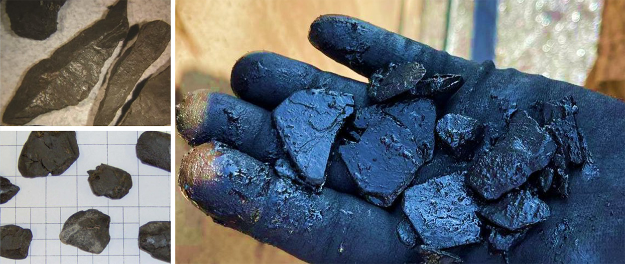
Validation of the geomechanical model typically involves leveraging drilling experience and ensuring that the model can explain the geomechanics-related events experienced in prior wells. For instance, stuck pipe, kicks or tight holes. Without validation, the model remains unconstrained, and decisions revert to guesswork. And guessing is expensive.