Taking a pressure measurement from thin sands can be a tricky exercise. Screenshot from composite well log of UKCS well 15/21b-50. Source: NDR.
Hunting for sands
How the depth accuracy of your formation tester is impacted by well design, tool-string configuration and mud rheology, and why this is more and more of an issue these days
If a school bus driver is instructed to stop the vehicle within a fraction of a meter, there needs to be systematic speed and brake control in place. Otherwise, the bus will likely overshoot or undershoot by several meters.
“The same is true for putting a formation tester at the right depth in a well,” says Guy Wheater, R&D manager at Gaia Earth Group, “especially when it comes to present-day deep and tortuous wells.”
The normal procedure for formation tester depth control is to tie it to a reference log from a previous logging run, carefully matching the gamma ray curves. In essence, it is a “dynamic correlation”. However, once the winch speed changes, the tool depth may no longer agree with what the winch panel says; the tool may stop deeper or shallower than required, via anti-creep or creep, respectively.
Creep occurs in deeper wells when the winch is stopped: The tool will keep moving in the direction of travel (up or down) until the tension along the cable equalises. Anti-creep occurs when the tool is grabbed by sticky formation, usually at slower speeds, and although the cable continues to be spooled on the winch drum, the tool is not moving.
HOW TO MEASURE CREEP?
A common way to estimate creep is to come up-hole and stop the tool 3 ft below the top of a definitive sand, followed by observing the raw gamma ray signal. If the reading ends up low, we are still in the sand, and we need to try again with a smaller distance. If the creep is estimated to be 2 ft, the tool is stopped at 15,002 ft for a pretest at 15,000 ft. This is an erroneous assumption because other transients may greatly affect the tool position: Lag, creep-down, tool-grab, cable stretch, spring, bounce, and finally, creep-up. Most of the non-creep transients are not currently considered or evaluated for formation tester depth control. From a dynamics perspective, a logging tool is just a “dumb-weight on the end of a long elastic band in a tortuous pipe full of gooey fluid” – it is a deeply complex system: The well depth, tortuosity, rheology, temperature profile and tool-string weight all drive up the transients and depth uncertainties.
“In shallow vertical wells with ample fluid bypass, using a simple and short formation tester in a 12 ¼” hole of 5,000 ft deep, you can reliably put the probe at the desired depth and gain consistent data, well to well,” Guy explains. “That’s because the Coulomb drag, cable stretch and creep are minimal, and the tool and cable stictions are generally low.”
When the cable stretch and stictions are high, the winch and tool movements may become decoupled. In fact, there may be periods when the cable and tools move in opposite directions along the wellbore. Furthermore, the tool acts as a piston in the mud column, damping and extending these decoupling events.
“The depth and complexity of wellbores and tool-string designs has progressed tremendously over time,” continues Guy. “For instance, large formation testers can now weigh over 9,000 lbf in air, the wellbores may be deep and tortuous and have large temperature spans, which impacts the rheology and mud gelling forces.”
Granted, in some places like the GOM, people do correct for tool-string creep, but downhole dynamics measurements over the last seven years have proven that creep is highly variable, and a uniform depth correction for each station is likely inaccurate.
In order to quantify creep, the team at Gaia used one of their own digital stand-off tools (WXSO®) that is fixed on the cable just 50 ft above the tool-string to better estimate tool-string and winch movements in a wellbore. When tool-string movement takes place, the WXSO® registers road noise via tri-axial accelerometers, which gradually fades when the winch is stopped. That gave the team an alternative method to compute creep time and distance.
There can be a large disconnect between people looking at NMR logs, doing very detailed sand and
shale assessments and coming up with very specific depths for pressure measurements, versus the reality where targeting certain sands in a given environment may be infeasible due to unfavourable dynamics, leading to winch-tool decoupling and depth errors. Clients should be aware of their environment and capacity for test point targeting in advance, and adjust their work plans if necessary
“We wanted to offer better creep estimates for upcoming jobs, based on well depth, trajectory, mud weight and tool-string dimensions,” explains Guy.
In order to pull together a database of measurements, the company collected data from eight wells drilled in the GOM, ranging in depth between 17-30,000 ft. “Intuitively, we expected more creep in deeper wells because of more stretch in the wire,” says Guy.
“Instead, we found uncorrelatable sets of data, to a point where we could not offer anything meaningful for creep corrections. We needed to take two steps back and conclude that what we had measured was real, and that larger events were happening downhole. Other transients were at play, with the capacity to dwarf creep itself,” says Guy.
“What most clients do,” he continues, “is to make a U-turn (down-then-up) to arrive at the desired station depth. The reason clients like doing that is because dropping off each station is a good stick test and also correlating up to the station can be routinely monitored. But whilst doing this U-turn, especially in deep and tortuous wells, a lot of things can throw you off depth.
MORE THAN PLANNED
Running the formation tester tool is usually the most time-consuming element of a logging programme. On a good day, with reasonable hole and permeability conditions, you can gain 5 to 6 pretests an hour, including a correlation pass. But because of winch-tool decoupling (off depth data) campaigns that have 40 tests planned can easily escalate to 60+.
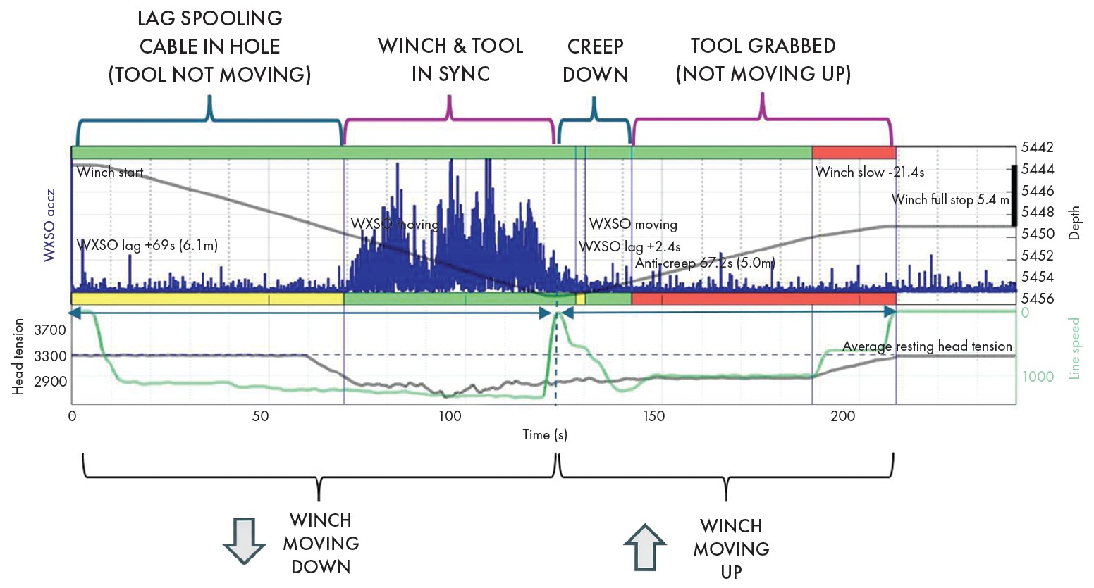
Let’s look at the plot below, demonstrating the conventional U-turn strategy, and how anti-creep can cause a major problem. First, we can see lag, then the tool and winch are in sync’, moving downhole together before the tool is grabbed and the cable is just being stretched coming up to station. In the end, the probe may be set >5 m deeper than planned, approximately 10 times what the creep correction might have been.
“We also think it is preferable to travel just in one direction (no U-turns), staying in a lower tension regime and keeping on depth real-time,” Guy says. “That way, you eliminate the majority of transients that may be induced from high-low-high tension cycling.”
Guy and his team are now building an advanced modelling package to simulate wireline dynamics and devise optimal survey strategies with bespoke winch controls. “In logging programs,” he says, “there is often talk about gauge stabilisation etc., but there is very little about depth control or winch driving. The potential savings in rig time and survey charges through detailed job planning and execution should be significant in deep or tortuous wells.”