In most prospective basins, the simpler and larger anticlines and high-side fault blocks have mostly been drilled. In order to find what is remaining, explorers can look for new trap types, such as low-side fault blocks and onlap or pinch-out traps.
The key questions in that case are how many different trap types may exist beyond the already existing ones, have they already been drilled before, and why were these unsuccessful. This requires an accurate definition of trap types.
However, in order to precisely define what a new trap type is, we need to look at the 3D picture. This immediately exposes the shortcomings of most trap schemes, as they are often a series of 2D cross-sections. In addition, different teams within the same company sometimes use different schemes, further adding to the potential for miscommunication.
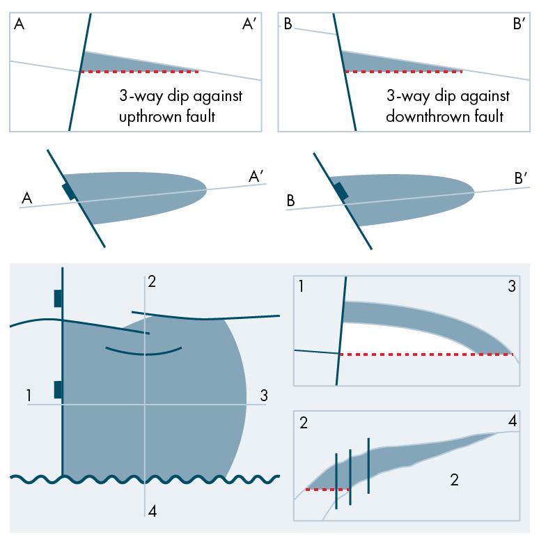
So, let’s take a look at an example here. Both examples in the top part of the figure are fault blocks, but they have a different risk profile altogether. The low-side example needs either the fault plane to seal or for the juxtaposed section in the footwall to be sealing, while the one on the left does not. In addition, we would also like to know how many other faults are involved since, intuitively, the more trap flanks that are faulted, the more risky the trap will be. On that basis, the term “Fault Block” for a trap type is useless; the complete 3D picture needs to be taken into account.
The second example shows how each prospect should ideally be evaluated, looking at all four sides, assisted by a map and two cross-sections. These are still generalised but do provide a much better assessment of the trap style by looking in all directions.
A solution to this problem is a systematic trap description scheme that can unambiguously define any conventional trap in 3 dimensions. One key aspect of the scheme is to classify the defined (4 flank) traps using the unofficial industry “Way Schemer” which has always been used. It has been expanded to include two types of 2-way traps, a 1-way trap and 0-way trap styles. This simple classification system, defined for the first time, helps better indicate risk and charge profiles, plus it helps find real analogues to the undrilled traps being evaluated.
This is the second of a series of articles based on work and experience from the GIS-Pax team in Australia, as presented by Ian Longley in a series of videos on LinkedIn.
Find the first article here .