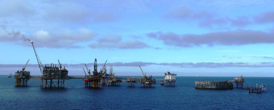
Ekofisk, Norwegian North Sea, was one of the first fields where time-lapse seismic proved an excellent tool for monitoring and mapping geomechanical changes in a producing field
A stone is ingrained with geological and historical memories.’ Andy Goldsworthy (Sculptor)
Studies at the Ekofisk field (Figure 1) have shown how reservoir compaction led to seabed subsidence of approximately 30–40cm a year over a long period (1986 to 1998), before the subsidence suddenly dropped to 15–20cm per year. Doornhof et al. (2006) explain this as a result of the chemical reaction between water and chalk. In 1987 a major campaign to inject sea water into the chalk reservoir had begun, the amount of water injected per day reaching a maximum level in 1996–1997. After a certain volume of a reservoir has been swept by water, chalk weakens to a given limit before the process slows down, which explains these changes in subsidence rate. In addition to this chemical process, we can observe that the average reservoir pressure started to increase again in 1994–1995, so possibly the sudden drop in subsidence in 1998 was caused by a combination of these two effects.
Figure 1: Ekofisk production and subsidence history. From 1987 to 1999 subsidence was between 30 and 40cm per year, corresponding to a total seafloor subsidence of more than 4m over this period. (Source: Doornhof, Kristiansen, Nagel, Pattillo and Sayers, Oilfield Review, 2006)
Figure 2: 4D time shifts for top reservoir interface (left) and for the Ekofisk Formation (right). The black area in the middle is caused by the gas chimney problem at Ekofisk, leading to lack of high quality seismic data in this area. Notice that some areas of the reservoir zone (right) are more compacted than others. (Source: Guilbot and Smith, TLE, 2002)
Furthermore, when subsidence is compared to reservoir compaction, the compaction rate is found to be higher than the subsidence rate; often a difference of 40–50% can be observed between the two, which means that overburden rocks are being stretched. Looking at seismic surveys over an area away from the crest of the field in the period from 1989 to 1999, Guilbot and Smith (2002) found that the top reservoir moved downwards by 4m, while the corresponding seabed subsidence was only 2.4m, meaning that the overburden rock had been stretched by 1.6m. From rock physics it is well known that such stretching will reduce the P-wave velocity of the rock, and hence will introduce an overburden time shift.
Guilbot and Smith (2002) used 4D traveltime shifts to conclude that the overburden at Ekofisk had been stretched and that the chalk reservoir rock was compacted due to production (Figure 2). A 4D traveltime shift means that the traveltime between two seismic horizons (representing geological interfaces in the subsurface) has changed. Guilbot and Smith found that the time shift for the overburden was up to 18 ms between 1989 and 1999. The overburden thickness at Ekofisk is approximately 3 km. This time shift was positive, meaning that the average P-wave velocity in the overburden had decreased between 1989 and 1999. For the same period they found a negative time shift of up to 10 ms for the Ekofisk reservoir formation, which was not a huge surprise since it was well known that the seafloor at Ekofisk had undergone severe subsidence. The compaction of the reservoir was also well known, and it was understood as well that the subsidence was less than the compaction at reservoir level, and hence the overburden has been stretched. What was new and exciting in Guilbot and Smith’s findings was that time-lapse seismic could be used to quantify compaction and thus to create maps that show that some reservoir compartments are more compacted than others. This initiated new research on how to couple geomechanical modeling with time-lapse seismic measurements.
Reservoir Compaction and Velocity Changes
When the reservoir rock compacts, the over- and underburden are stretched. This stretch is relatively small (of the order of 0.05%). However, it produces a small velocity decrease that is observable as time shifts on time-lapse seismic data.
A simple calculation can help us to understand why timelapse seismic can detect such small changes. Assume that the velocity decrease caused by the stretching of the overburden is -0.1%. As an example we can assume that the average velocity of the overburden thickness is 2,000 m/s, and that the overburden is 3,000m. After stretching, the velocity is 1,980 m/s. The difference in two-way traveltime is then (neglecting the length change of the overburden):
T2–T1 = (6,000m ÷ 1,980m/s) – (6,000m ÷ 2,000m/s) = 0.03s = 30ms
which is well above detectable time shifts (less than 1 ms for high quality time-lapse seismic data). If the fact that the thickness of the overburden is also changed is taken into the equation, the following relation might be derived (assuming that the stretch dz is much smaller than the overburden thickness (z) and that the velocity change dv is much smaller than v – see Landrø and Stammeijer, 2004):
dT/T = dz/z – dv/v
When the rock is stretched, dz is positive, and dv is negative, which means that the two terms on the righthand side in this equation enforce each other. In the first example we found that the velocity change caused a 30 ms increase in two-way traveltime. If we assume that the reservoir compacts by 10m and that the subsidence at the seafloor is 7m, the total stretch of the overburden is 3m, and the first term on the right side in the equation is 3/3,000 = 0.001, corresponding to 3 ms, which is significantly less than the velocity effect in this case.
Figure 3: Estimated compaction of the chalk reservoir at Ekofisk between 1989 and 1999 neglecting overburden velocity changes (right) and including the changes (left). Notice that the two plots have different spatial distributions, not just a scalar difference between them. (Source: Guilbot and Smith, TLE, 2002)
Guilbot and Smith (2002) show two maps of estimated reservoir compaction at Ekofisk, one without taking the overburden changes into account and one where the effect is included (Figure 3). The difference is significant, and it clearly demonstrates that the assumption of a constant overburden is not correct for the Ekofisk 4D case. Both in magnitude and spatial distribution, the two maps are very different.
Røste et al. (2005) assumed that the relative velocity change divided by the relative stretch is given as a constant, α. For the example given above α = -10. Also in 2005, Hatchell et al. introduced essentially the same parameter, denoted R, where R = -α. For a compacting reservoir, the P-wave velocity will increase and the thickness decrease, hence again, the α value will be negative. This factor is often referred to as the dilation factor.
If α or R is known, we observe from the equation above that when the 4D time shift is measured, both the velocity changes and the thickness changes can be estimated.
Compaction in Clastic Reservoirs
Figure 4: Estimated time shifts for the Snorre overburden. Note the negative time shifts (velocity slow down) of up to 3 ms. (Source: Røste et al., TLE 2015)
It is well known that highly porous chalk fields compact, but what about clastic reservoirs? In the North Sea both Elgin and Franklin, which are HPT (High Pressure and Temperature) fields, show significant compaction, although not as much as chalk fields. In a recent paper Røste et al. (2015) report that the Snorre field exhibits compaction and that overburden time shifts of the order of 3 ms have been observed between 1997 and 2009, as shown in Figure 4.
Compared to Ekofisk, these time shifts are significantly smaller, by a factor of 6, underlining the fact that clastic reservoirs compact less than chalk fields. For a sandstone reservoir, the chemical effect (water weakening) is probably negligible, so it is fair to assume that the reservoir compaction is mainly pressure driven. Apart from this, the mechanism for the stretching of the overburden rocks is the same.
A vertical profile showing that the time shifts reach nearly up to the seabed and that the width of the anomaly is more than a kilometer is shown in Figure 5. From the time shift estimates, it is possible to estimate velocity changes, which might be compared to geomechanical modeling. Notice the arching effect (the variation in overburden vertical stress caused by the reservoir compaction); stress arching occurs if the compaction zone is finite (for an infinite reservoir without edges there will be no arching effects) and some of the overburden weight is transferred to the sides of the reservoir, as illustrated in Figure 6. Due to the finite size of the compacting compartment, there will be edge effects where the vertical stress close to the edge of a reservoir increases, while there is a decrease right above the crest of the compartment.
Figure 5: (a) Estimated time shifts between 1997 and 2009; note that the time shifts extend almost to the water bottom, which is at approximately 300m. (b) Estimated velocity changes. Notice four distinct areas (1–4), where 1 and 3 show a velocity decrease, 2 no change and 4 a velocity increase, probably caused by stress arching. (c) Estimated velocity changes – the velocity increase marked 4 in (b) is interpreted as a stress arch effect. Modeled velocity change (using geomechanical modeling) assuming α = -20. (Source: Røste et al., TLE 2015)
Figure 5: (a) Estimated time shifts between 1997 and 2009; note that the time shifts extend almost to the water bottom, which is at approximately 300m. (b) Estimated velocity changes. Notice four distinct areas (1–4), where 1 and 3 show a velocity decrease, 2 no change and 4 a velocity increase, probably caused by stress arching. (c) Estimated velocity changes – the velocity increase marked 4 in (b) is interpreted as a stress arch effect. Modeled velocity change (using geomechanical modeling) assuming α = -20. (Source: Røste et al., TLE 2015)
Figure 5: (a) Estimated time shifts between 1997 and 2009; note that the time shifts extend almost to the water bottom, which is at approximately 300m. (b) Estimated velocity changes. Notice four distinct areas (1–4), where 1 and 3 show a velocity decrease, 2 no change and 4 a velocity increase, probably caused by stress arching. (c) Estimated velocity changes – the velocity increase marked 4 in (b) is interpreted as a stress arch effect. Modeled velocity change (using geomechanical modeling) assuming α = -20. (Source: Røste et al., TLE 2015)
Stress arching and in general stress changes in the overburden might cause problems for well bore stability, and there are several examples where wells have failed due to severe overburden stress changes. Hence, it is important and useful to monitor and map these overburden changes for a producing reservoir and, as these examples show, time-lapse seismic is an excellent tool for this.
Figure 6: Stress arching: if the weight of the overburden is transferred to the sides of the reservoir (right) we get a stress arching effect. On the other hand, if the weight of the overburden does not transfer to the reservoir we have a situation like the lefthand figure. (Source: Modified from Schutjens et al., 2010)
References
Bathija, A.P., Batzle, M. L. and Prasad, M. 2009 An experimental study of the dilation factor. Geophysics 74, E181-E191.
Fjær, E., Holt, R.M., Horsrud, P., Raaen, A.M. and Risnes, R. 2008. Petroleum Related Rock Mechanics, 2nd edition. pp402-409. Elsevier, ISBN 978-0-444-50260-5.
Han,D., A. Nur and Dale Morgan, 1986. Effects of porosity and clay content on wave velocities in sandstones. Geophysics, 51, 2093-2107.
Holt, R. M., Fjær, E., Nes, O.-M. and Stenebråten, J.F. 2008. Strain sensitivity of wave velocities in sediments and sedimentary rocks. ARMA (American Rock Mechanics Association; conference paper) 08-291, 1-8.
Landrø, M. and Stammeijer, J. (2004). Quantitative estimation of compaction and velocity changes using 4D impedance and traveltime changes. GEOPHYSICS, 69(4), 949-957.
Røste, T., O.P. Dybvik, O.K. Søreide, 2015, Overburden 4D time shifts induced by reservoir compaction at the Snorre Field, paper submitted to The Leading Edge.
Schjutjens, P. , J. Snippe, H. Mahani, J. Turner, J. Ita and T. Mossop, 2010, Production-induced stress change in and around a reservoir pierced by two salt domes: A geomechanical model and its applications, Devex, Aberdeen.
Settari, A. 2002. Reservoir compaction. SPE paper 76805,62-69.
Tempone, P. 2011. Effects of reservoir compaction on seismic and gravity monitoring. PhD thesis, NTNU, 2011:6, ISBN 978-82-471-2519-9.