Carbon dioxide (CO₂) is not a popular gas these days. Industry, governments and even individuals are actively trying to reduce its production, and dispose of what is produced, in such a way that it disappears forever. Over the last decade or more, the capture and disposal of CO₂ has created a whole new industry dedicated to finding ways of capturing and storing the unwanted gas and preventing it entering our atmosphere. Meanwhile, E&P companies are reorientating themselves to become waste-disposal services, by offering existing infrastructure and ‘empty’ storage facilities.
Both in the North Sea arena and globally, much technical, logistical and planning effort is focused on the use of carbon capture and storage (CCS) methods to dispose of unwanted CO₂, both in depleted gas fields such as those of the Southern North Sea Basin, or in saline aquifers such as exist in the Central North Sea Basin. There are also enthusiastic advocates for the use of the proposed unwanted volumes of CO₂ to be used in CO₂ enhanced oil recovery (EOR) from mature fields. The US has employed CO₂EOR for over a decade with good results, and there are those who seek to replicate this in the North Sea.
Who Uses What and Where?
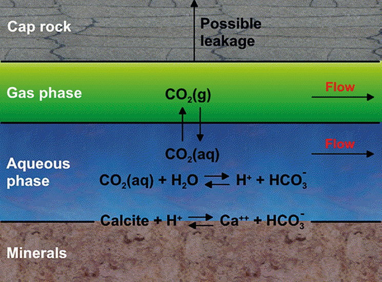 Figure 1: Physics of CO₂ storage. © CMG.CCS and CO₂EOR are both good ideas, but good ideas do not always come with all the practicalities nicely packaged. The reality of the North Sea presents specific constraints and considerations, linked to water depths, well location and well spacing; and in the northern North Sea area particularly, extreme weather conditions exist.
Beyond E&P, much of industry sees the injection of CO₂ into ‘vast caverns beneath the sea’, as a ‘cure-all’ to their CO₂ problems. The perception of CO₂ disposal is too often an injection well into an infinite hole below ground, and preferably, beneath the sea….
From the E&P side, that same injection well is a conduit into the unknown, with highly corrosive CO₂ damaging piping and casing integrity; and the same highly reactive CO₂ entering the saline aquifer or depleted gas reservoir and interacting with the existing fluid and rock chemistry. In contrast, if the reactive potential of CO₂ is to be utilised in EOR, it should be remarked that the injected CO₂ is used to sweep the reservoir, and thus goes down the injection well, only to subsequently come back up the production well, where it needs to be recaptured.
The objectives of CO₂ storage and CO₂EOR are very different. The motivation for CO₂ storage is to reduce greenhouse gases utilising depleted oil and gas reservoirs and also saline aquifers. CO₂ is highly soluble in the aqueous phase and saline aquifers have a large capacity to store it (Figure 1). The motivation for CO₂EOR, by contrast, is to increase the recovery factor of an oil reservoir subsequent to primary depletion and secondary water flooding. As heavy industry seeks to capture CO₂, the E&P industry now perceives a reliable future supply of CO₂ for EOR practice where the reservoir formation and fluid characteristics are suitable. Are CO₂ storage and CO₂EOR competing concepts, or a mutually beneficial arrangement?
Basics of CO₂ Storage
CO₂ is trapped underground and contained therein by different mechanisms, each acting over a different timescale. Reservoir simulation is utilised to model, evaluate and manage the CO₂ injection strategy, and predict the movement of the gas in the subsurface where it becomes trapped and stored. The mechanisms include:
Structural Trapping: The CO₂ is trapped as a mobile gas (super critical fluid) in the geological structure, by an impermeable cap rock. What had applied as a physical trapping mechanism for the hydrocarbons in a depleted reservoir also applies to CO₂. Continued injection of CO₂ increases the subsurface pressure, and careful fracture, resulting in the CO₂ leaking upwards and away (Figure 2).
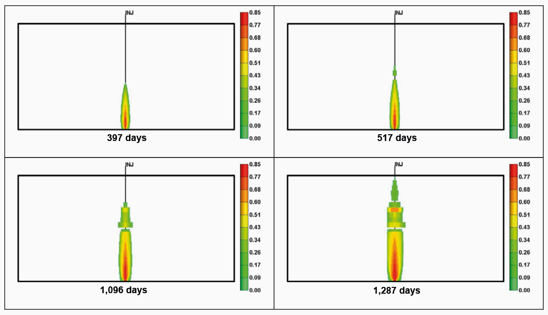
Figure 2: Evolution of gas saturation in the aquifer and in overlaying formations due to leakage through caprocks. (SPE 125848 Nghiem et al 2009). © CMG.
Residual Gas Trapping: Depending upon CO₂ movement, (drainage or imbibition), and hysteresis effects, CO₂ can be trapped as an immobile gas in the pore space. This method is most effective in low-permeability aquifers and is accelerated by water injection.
Solubility Trapping: CO₂ is highly soluble in brine and becomes a soluble component in the aquifer brine. Aquifers ‘flow’ underground, albeit on extended timescales, so there is the potential for migration of the CO₂ -rich water out of the designated injection or storage area.
Mineralisation: As the dissolved CO₂ content of the aquifer brine increases, so does the acidity of the brine. This leads to dissolution of some rock minerals, and deposition of carbonate minerals such as calcite, dolomite and siderite. In other words, the injected CO₂ is bound into a solid physical state. This is the safest storage mechanism, but there are many uncertainties in predicting when and where dissolution and precipitation may take place in the subsurface.
Residual Gas Trapping and Solubility Trapping are the most important CO₂ trapping mechanisms (Figure 3). High-permeability aquifers favour Solubility Trapping while low-permeability ones favour Residual Gas Trapping. Reservoir engineering techniques can be used to accelerate and increase the amount of Residual Gas Trapping. Reservoir simulation coupled with geomechanical simulation must be undertaken to determine and manage structural integrity, as demonstrated in Figure 2.
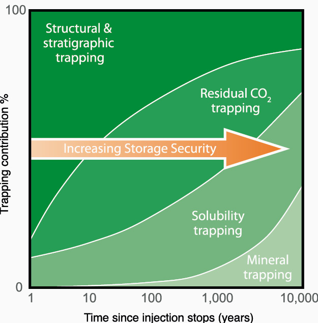
Figure 3: Security of CO2 storage versus time. Metz et al., ICCP Report 2005.
The Basics of CO₂EOR
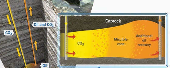
CO₂ may be injected into a reservoir as a form of EOR process, typically either CO₂WAG (CO₂ plus high salinity water) (Figure 4), or CO₂LSWAG (CO₂ plus low salinity water). Note that in the US onshore unconventional plays, CO₂EOR takes the form of ‘huff and puff’, a process not applicable in the North Sea. Injected CO₂ develops miscibility through multiple contacts with the reservoir oil. A certain pressure is needed to achieve miscibility, which is called the minimum miscibility pressure (MMP).
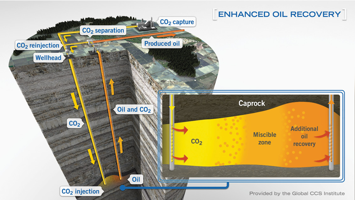
Figure 4: Enhanced oil recovery using CO2. Global CCS Institute.
Above its critical conditions (7,390 kPa, 31°C), the density of CO₂ is in the range of the reservoir oil density, but its viscosity is less, which results in an unfavourable mobility ratio. Injecting CO₂ swells the oil and the saturation pressure changes. Increasing the CO₂ injection pressure above the MMP increases the CO₂ density, resulting in better sweep efficiency and a higher oil recovery.
When designing a CO₂EOR project, there are multiple considerations, including the reservoir formation; the PVT of the hydrocarbon fluid; the reservoir heterogeneity and thus overall permeability distribution. Of particular importance is the vertical permeability and associated potential for CO₂–oil segregation. Offshore, inter-well distance is crucial, with the potential to fall below the miscibility pressure and lose the flood efficacy. Other factors such as water blocking, viscous fingering, hysteresis and asphaltene precipitation must also be considered. Reservoir simulation is an essential part of the design phase and subsequent evaluation of the success of the miscible flood process; type of flood, flow mechanism, (vertical flood or gravity segregation), WAG or LSWAG and slug size. Asphaltene deposition can lead to permeability reduction and plugging especially around the well area, and as with infrastructure corrosion, is an undesirable effect of injecting CO₂.
Competing – or Mutually Beneficial?
When designing a CO₂ storage project, optimisation focuses on the location of the injector wells, the injector rate, injection pressure and the duration of the injection period. When designing a CO₂EOR project, these parameters are also the focus, but for different reasons. Injection during CO₂ storage is most likely to be continuous, (supply dependent), and will continue for years or decades, with the aim of injecting in such a way as to maximise trapping of the CO₂ in the reservoir. Thus injector location, and injection rate and pressure, are designed to optimise residual gas trapping and solubilisation of the CO₂ in the reservoir brine. Conversely, in a CO₂EOR project, the CO₂ will not be injected continually, but in a series of pulses, with the aim to recover as much of the injected gas as possible, both for re-injection, (supply dependent), and because the less CO₂ that is trapped in the reservoir, the more effective is the hydrocarbon recovery process.
Storage of CO₂ and use of it as an EOR agent are different subsurface processes. This does not mean that they cannot be managed together, either as sequential field operations, or as separate operations in different reservoir compartments. It is for those working on the projects to access accordingly. The discussion here is necessarily simplistic, with the intention of raising some of the practicalities of injecting CO₂ into the subsurface, whether to dispose of it in the long term, or to gain additional value in enhanced hydrocarbon recovery in the short term.
References
Metz, B., Davidson, O., de Coninck, H., Loos, M., and Meyer, L. (eds), IPCC (2005). Carbon Dioxide Capture and Storage. Cambridge University Press.
Nghiem L., Shrivastava V., Tran D., Kohse B., Hassam M. and Yang C. (2009). Simulation of CO2 Storage in Saline Aquifers. 2009 SPE/EAGE Reservoir Characterization and Simulation Conference.