High-Resolution Image-Guided Tomography
High-resolution image-guided tomography (IGT) can be used to resolve the complex structure below a shallow trench in the Gulf of Mexico.
The Nessie project is a full-azimuth ocean-bottom node survey located in the ultra-shallow water of the South Timbalier trench area of the Gulf of Mexico, an area known for complex static problems. These are often addressed in the time domain by applying time shifts generated from a refraction statics solution. In the depth domain, however, the same time shift will produce kinematically incorrect depth migration results and can lead to velocity distortions during successive tomography-based model building.
The problem is instead addressed in the depth domain by high-resolution tomography. The high frequency nature of the surface consistent residual statics is difficult to resolve via tomographic inversion; therefore this portion of the statics is instead applied to the data prior to depth migration.
The final depth-imaging results demonstrate significant uplift, with accurate images, improved image focusing, correctly positioned steeply dipping events and better well-to-seismic ties. The improvements are due to proper well-to-seismic calibration, anisotropic parameter estimation and multi-azimuth tomographic inversion. Offset-dependent event picking and geologically constrained image-guided tomographic inversion further enhance the image quality.
Initial Anisotropic Model Building
The time-RMS model derived from PSTM velocity analysis was the starting velocity model for the project. The velocity model was converted to the depth-interval velocity domain, and an isotropic shallow tomographic inversion was run before calibration with checkshots, twenty-two of which were selected for this purpose. Anomalous trends were edited before using them for calibration. Scalar functions were derived at checkshot locations to match the migration velocity to the checkshots and these scalar functions were interpolated and extrapolated along key interpreted horizons. A scalar grid was produced from the fully interpolated scalar functions in order to match the migration velocity field to the checkshots.
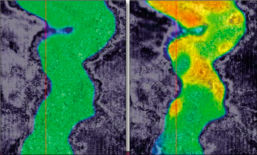
Prestack depth migration was performed with the calibrated velocity model. A lack of checkshot information in the trench area meant the velocity model did not reflect the low velocity trend present in the trench. This lack of slow velocities resulted in a migrated image with a significant structural sag (Figure 1).
To ensure tomographic velocity convergence, a slow velocity trend was manually inserted in the trench area. A constant velocity value of 1,350 m/s was inserted in the region between the water bottom and an interpreted base of trench and successive iterations of high-resolution shallow tomography would further refine the velocity model in this region. Outside of the trench the previously calibrated model was used as an initial vertical velocity model VZ for the subsequent model building process.
An isotropic Kirchhoff prestack depth migration was run using the resulting VZ model. Since the model matched the checkshot velocities at checkshot locations, residual moveout at these locations is attributed to anisotropy. Therefore, common image gathers (CIGs) at the checkshot locations were then fed to a focusing analysis tool to derive anisotropic parameters δ and ε at the well locations, which were edited and smoothed to identify a general trend for the study area. Since the project area was relatively small, a single δ and ε function is sufficient for the entire area. To this end a single average function which best represented the anisotropic function in the study area was derived and extrapolated along the previously interpreted horizons to generate fully populated δ and ε volumes for the successive anisotropic model-building and depth-imaging processes.
TTI Model Building
The initial VZ model and the derived anisotropic parameters can be used to convert vertical velocity VZ to normal velocity V0 for anisotropic depth migration. The initial 3D dip fields were generated from an isotropically migrated stacked image volume and fed into the TTI depth migration flow.
Shallow Trench Tomography
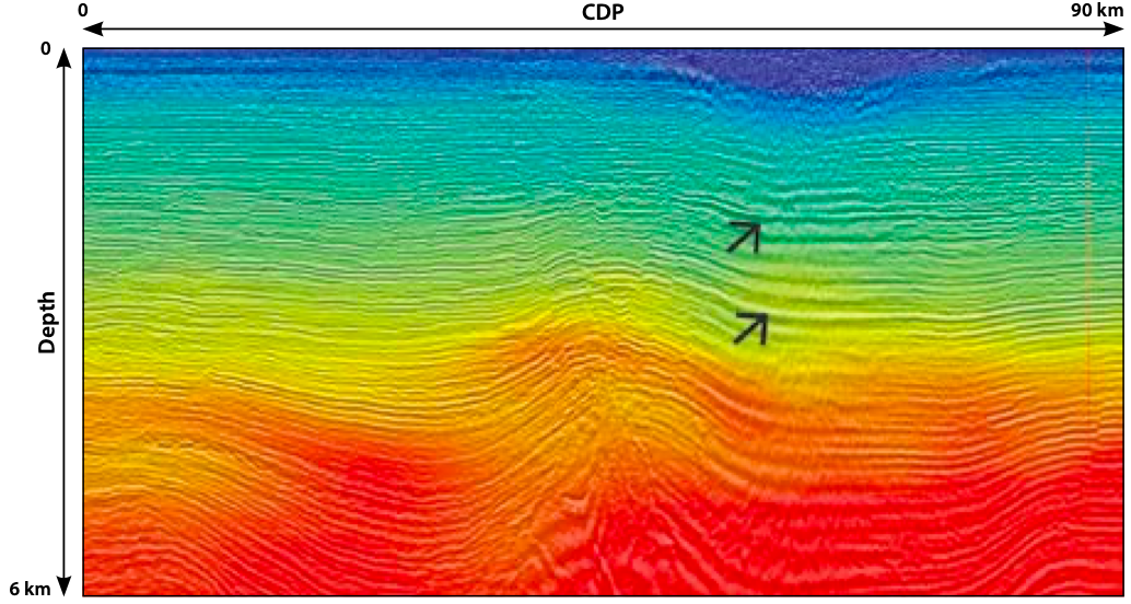
The 3D OBC data was then azimuthally sectored during the binning process, to ensure the full azimuthal illumination of the study area. The input data was divided into six azimuths, each of which was migrated using TTI prestack Kirchhoff depth migration. To ensure a high-resolution model update at very shallow depths and in the trench area, a finer tomographic inversion grid was adopted. Single parameter curvature-based residual moveout (RMO) was picked on scanned semblances derived from TTI PSDM CIGs. We noted that a positive curvature (increasing reflection depth with increasing offset) was picked in the trench area, which translates into a velocity decrease. This velocity slowdown is consistent with what is expected for unconsolidated gas-charged mud. Velocities as low as 1,000 m/s resulted after two tomographic updates (Figure 2).
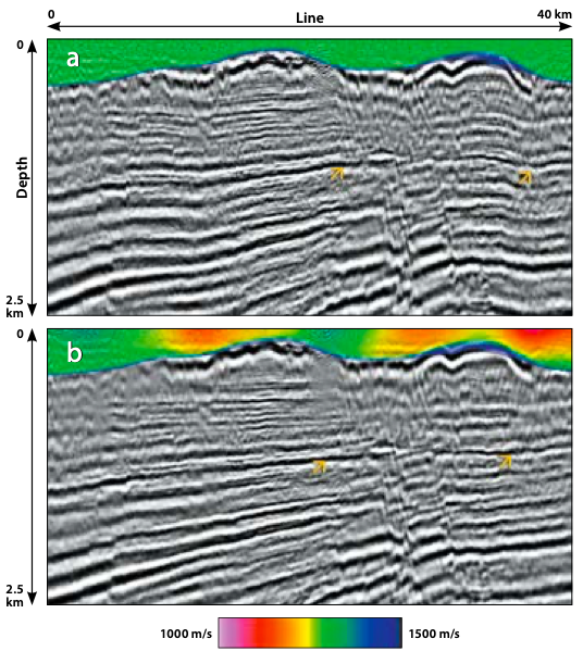
The tomographic updates not only better flattened the CIGs, but dramatically diminished the structural sag (Figure 3). Additionally, faults are better focused, all of which gave more confidence that the velocity updates were converging towards a correct velocity model.
High-Resolution, Image-Guided Tomography Update
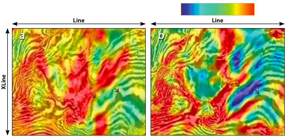
A higher resolution, geologically conformable model update was achieved by offset-dependent RMO picking and image-guided tomography (Hale, 2009; Hilburn et al., 2014). Offset-dependent picking is a robust process utilizing an event-finding technique which is guided by analyzing amplitude variation between traces in the CIGs, geological dips, continuity of the reflector, displacement of events within gathers and a required flatness-constraint (Hilburn et al., 2014). This procedure honors events with complex moveout patterns well. More accurately sampling the residual depth error should also allow for better resolution in the velocity model.
The directionality and continuity of events were employed to calculate a set of tensors that are used to define update zones whose boundaries are computed by minimizing structure-oriented propagation time within the underlying image. Disruptions in this propagation time identify the coherent and incoherent structures (e.g. faults). The zonal distribution, computed tensors and the propagation time combine to describe a preconditioning operator for the tomographic inversion. This higher resolution and geologically conformable IGT update produced a higher resolution background sediment velocity model (Figure 3) for depth imaging.
Acknowledgements
We would like to thank TGS management for permission to publish this paper. We would also like to thank Ashley Lundy, Kenny Lambert, Steve Hightower, George Cloudy Jr., Bin Wang, and Zhiming Li for their support and suggestions, and Connie VanSchuyver for proofreading the manuscript. The Nessie survey is a cooperative project between TGS and FairfieldNodal.