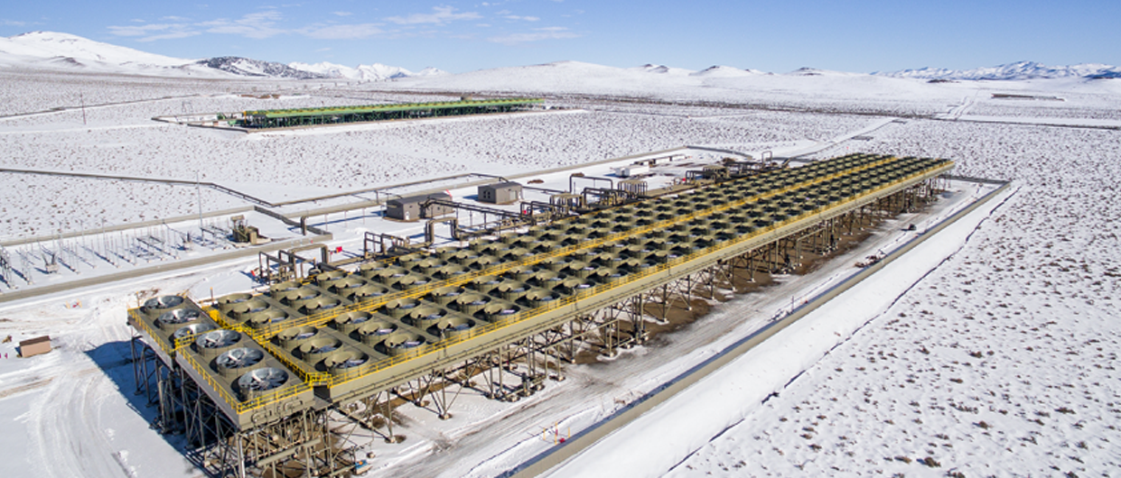
Pumped-well geothermal projects utilize “binary” power plant technology which consists of Organic Rankine Cycle (ORC) heat exchangers. The geothermal fluid is pumped from the wells as a single phase liquid throughout the process of pumping, heat exchange and re-injection.
There are several types of pumps available, including line shaft pumps (LSPs) which have the electric motor on surface and the pump impellor downhole with a rotating shaft connecting the two, and electric submersible pumps (ESPs) with both its motor and impellor located downhole. LSPs are by far the most commonly used in pumped-well power projects, although ESPs are required where the depth of the impellor precludes the use of a line shaft.
The essential purpose of the pump is to boost the pressure at the impellor intake sufficiently to maintain the fluid in single phase and provide the pressure and flowrate required at the plant inlet. There are often additional booster pumps either in the plant or prior to re-injection.
The impellor intake must be set deep enough below the static water level such that the water level above the pump while pumping, defined here as the dynamic head, provides sufficient pressure to prevent cavitation in the pump (i.e. prevent boiling or gas bubbles forming in the liquid phase).
This depth is primarily controlled by the fluid temperature and productivity index (PI). PI is defined in Article I of this series as the volume flowrate per unit pressure, which determines the drawdown. To keep the fluid in single phase the allowable drawdown cannot be exceeded and the pressure in the fluid cannot fall below the vapour pressure of water (the pressure at which the fluid will begin to boil).
This is the second article in a series on Geothermal pumped-well power projects. The first article included a global overview of operating projects and subsurface characteristics. This article focuses on pump hydraulics, the third will cover energy conversion and the fourth will deal with economics and emerging technology.
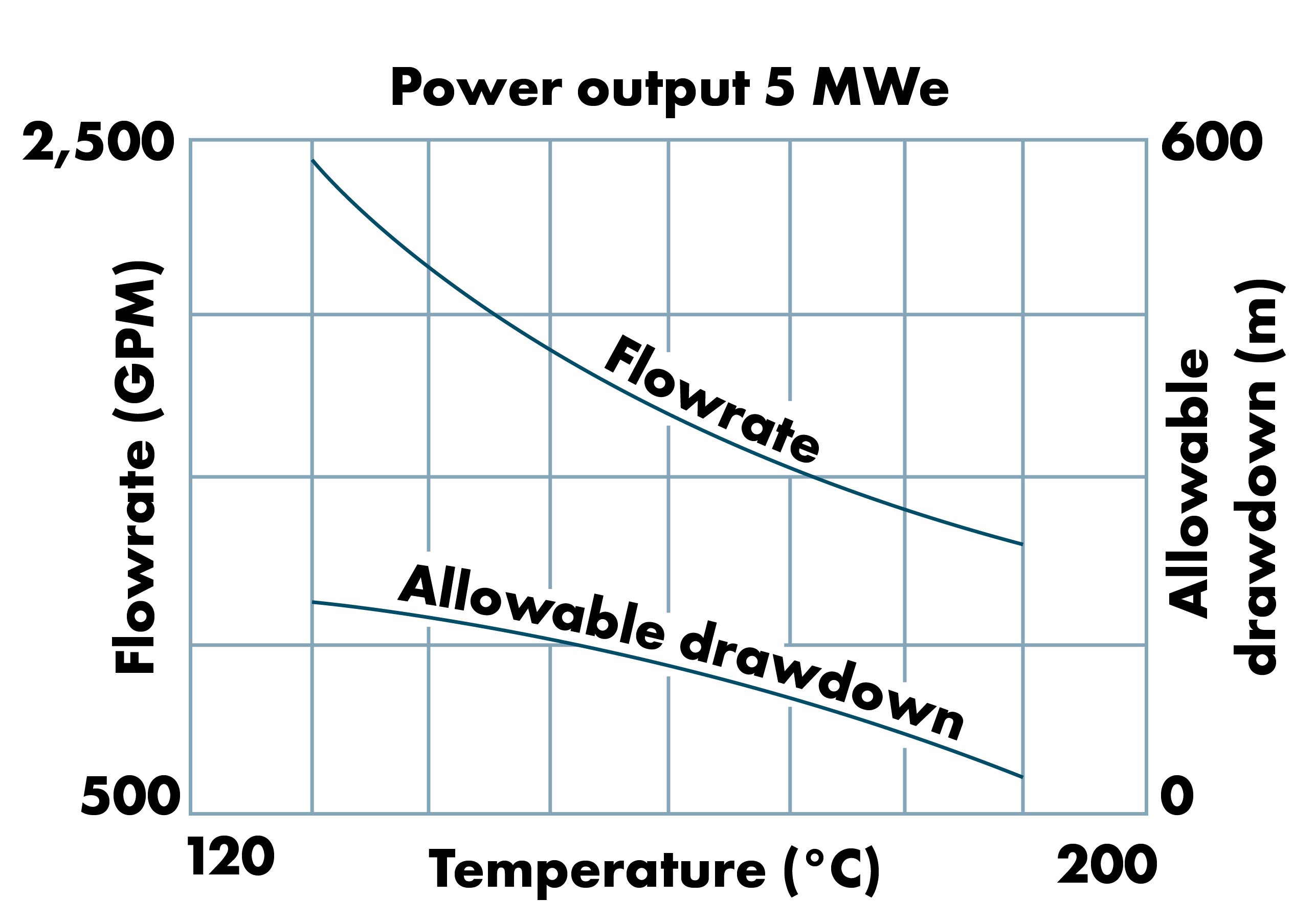
The temperature determines the vapour pressure of the fluid, which is a primary factor controlling allowable drawdown, as the hotter the fluid the higher the vapour pressure and lower the allowable drawdown (Figure 1).
Figure 1 illustrates that the required flowrate for any given power output (in this case 5 MWe) decreases with temperature but the limit for allowable drawdown is reached about 190C. This relationship is also dependent on the static water level and PI, however the vapour pressure of water increases non-linearly such that 190C is usually the practical limit for pumped-well projects.
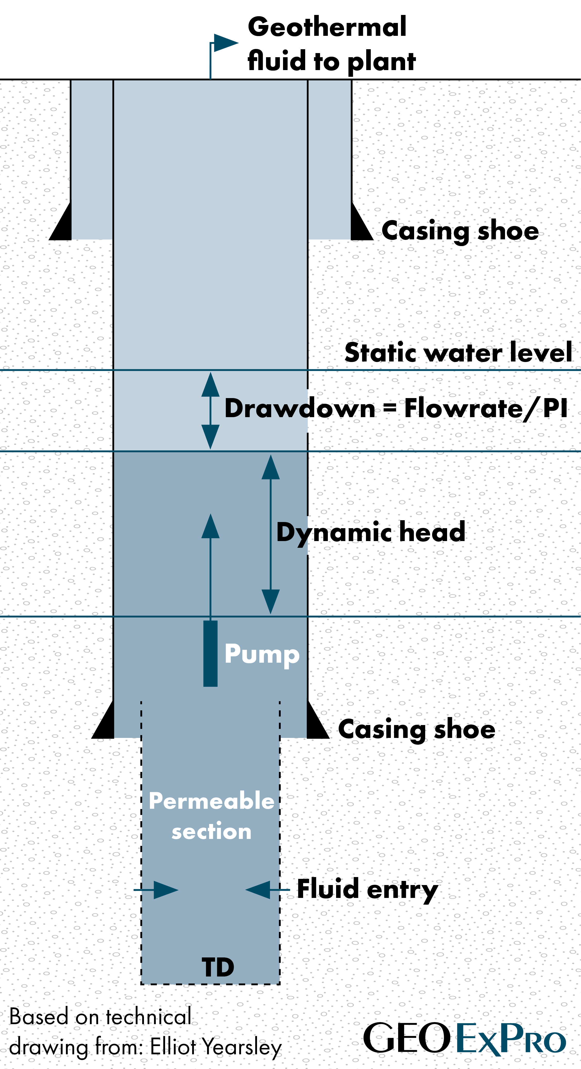
The schematic shown in Figure 2 illustrates the key hydraulic parameters for a pumped well; namely:
- Static water level (water level without pumping)
- Dynamic head (water level above the pump while pumping)
- Drawdown (difference between static and pumping)
The pump impellor stages are set inside casing above the casing shoe and fluid entry is from the perforated liner below the shoe. Pumped wells in the western U.S. are completed comparatively shallow with permeable zones usually between 500-1,500 meters and pump set depths between 300-500 meters. Pumped wells in Europe tend to have deeper reservoirs and in some cases the pump must also be set deeper.
Elliot Yearsley – enyearsley@gmail.com