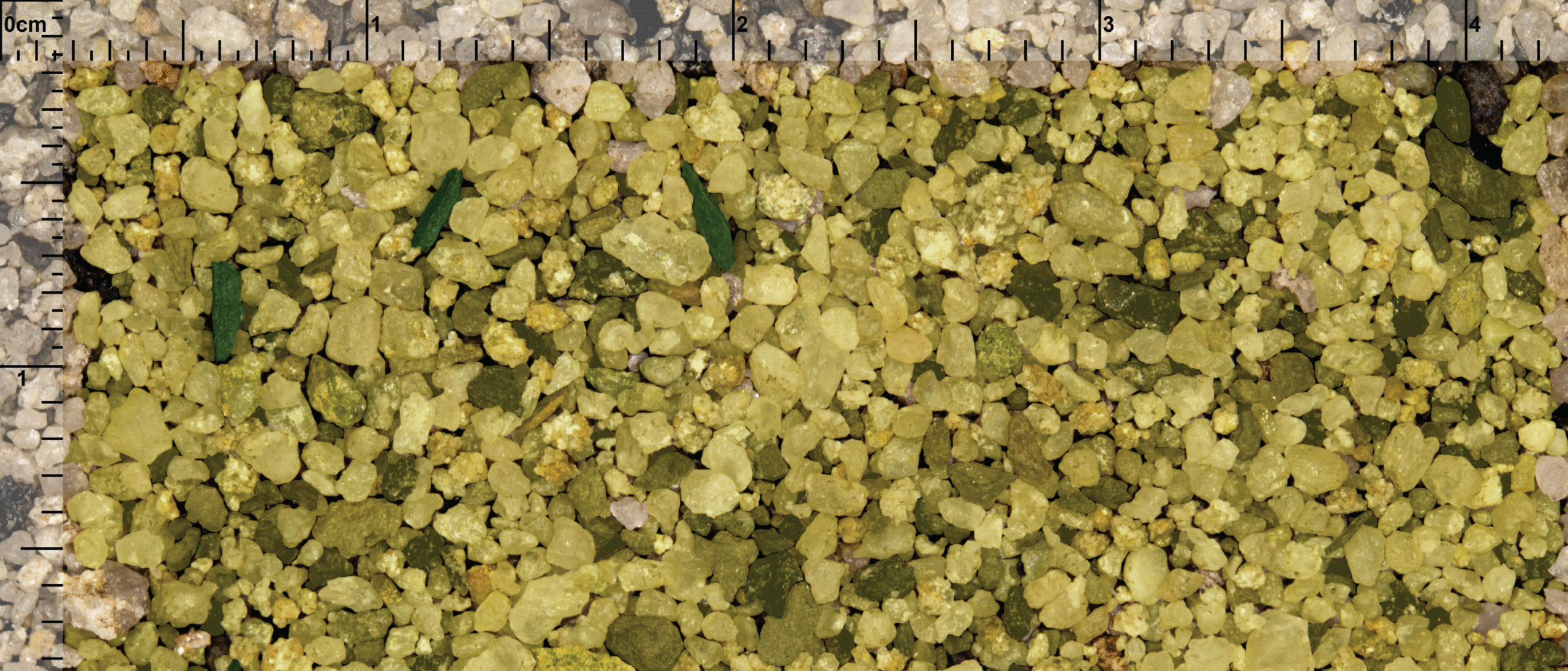
From the early days of hydrocarbon exploration, right up to the present day, the ‘traditional’ method of finding the geological or stratigraphic position of a well while drilling has been to look at the rock samples or ditch cuttings that come to the surface. Drill bits grind up the rock they are penetrating and the cuttings are carried up by the returning drilling mud. Geologists called mudloggers extract the samples from the shaker tables, the sieves that separate solid particles from the mud, calculate their depth of origin in the well and analyze them under a microscope. From this they can determine the overall mineralogy of the samples and, combined with other data such as the presence of micro-fossils, work out the overall lithology and geological age of the samples.
In many cases, these measurements are supplemented by rock property information from measurement while drilling (MWD). These direct views of the rocks that are being penetrated are often the only way to determine the stratigraphy unless more costly techniques like coring are employed. But there is a limit to the accuracy and detail that can be obtained by looking at the samples under a microscope. The results are also highly dependent on the knowledge and experience of the mudlogger and well site geologist, as they are essentially from visual observation backed up by some basic analysis of the drilling parameters.
The lithology description provided by mudloggers is essential while a well is actually being drilled, but it is often not sufficient to provide the detail of the mineralogy and other rock properties needed by, for example, petrophysicists, geologists and geophysicists studying detailed reservoir behaviour. So the samples from the well site are not discarded, but bagged up and sent to specialist geological laboratories for further analysis. Often, this analysis may be done in great detail, at a submicron level, using a Scanning Electron Microscope (SEM). As well as providing very detailed images, these devices also make other measurements of the samples such as their BSE (back-scattered electron) and characteristic X-ray signals (energy-dispersive X-ray or EDX spectrum). These signals are distinct for different chemical compositions and so can provide the basis for automated and very accurate mineralogy and lithology determinations.
SEM analysis can provide valuable information about rock properties, though in most cases this comes too late to influence operational decisions, as the measurements are made using bulky and sensitive equipment in labs, usually long after drilling is complete. But now it is possible to take a ruggedized SEM to the most remote well locations to provide fast and accurate lithology descriptions while a well is drilling, using a system called QEMSCAN® WellSite™ developed by FEI.
FEI is a leading developer and manufacturer of electron and ion beam microscopes. It has a business unit, ‘Natural Resources’, that is dedicated to the geoscience sector, including the oil and gas business, and has developed a suite of applications based on an SEM with resolution down to 1 micrometer called QEMSCAN (quantitative scanning electron microscope) which uses a proprietary ‘Spectral Analysis Engine’. This ‘engine’ first analyzes the elemental composition of samples by comparing the measurements to standard reference sets and then uses a statistical analysis method (Species Identification Protocol – SIP) to identify and quantify the mineral composition. This method has proved to be effective in the identification of minerals including clay minerals and is also able to distinguish between, for example, minerals lining pores and intergranular cements.
Taking SEM to the Well
FEI has made a portable version of the QEMSCAN that can be taken to remote locations by helicopter or even on the back of a small pickup truck. A specially optimized sample preparation workflow has also been developed that is suitable for field use, rather than standard SEM techniques that require laboratory conditions. Cuttings samples are sieved to the required size, for example between 2mm and 63 microns, washed and dried with a microwave oven. The samples are mixed with epoxy resin, which is cured into a cylindrical block that is then cut into sections by a diamond saw. The samples are coated with a thin layer of electro-conductive carbon to prevent charging by the electron beam of the microscope. Each sample section is scanned by the microscope on a grid at a rate of up to 200 measurements per second, building up, over a measurement time of some 30 minutes, about 400,000 measured points per set of samples.
Data processing on the measurements using the Spectral Analysis Engine and SIP method then takes place offline and produces images of the results together with a detailed mineralogy log and lithology log based on standard classifications. One of the advantages of this QEMSCAN WellSite system is that it can identify and remove the effects of contaminant and additive particles automatically so that the results are based only on genuine geological samples. In a field test conducted recently in a remote location in Papua New Guinea, the system was able to keep up with drilling, averaging 23 sample sets a day, with the most continuous run being 728 samples in 34 days.
Nanoscale Resolution
The concept of taking a scanning electron microscope into remote field loca tions and producing a detailed mineral ogy log in real time is certainly impressive. But there are situations where even micron-scale resolution is not enough. These may be when analyz ing unconventional ‘tight’ reser-voirs such as the Marcellus Shale in the north-eastern US. Here, to achieve resolu tion down to a few nanometers, which is necessary to look at detailed 3D pore geo metry and the fine details of mineralogy, new high resolution micro scopes such as Field Emission or Focused Ion Beam Scanning Electron Micro scopes (FEG-SEM and FIB/ SEM) are required. FEI manu factures these devices too, with the FIB/SEM technology produced under the name DualBeam™.
These complex devices are still for laboratory, not field work. But in looking at the results, FEI also addresses the problem of how to go back to the basics of a representative wellsite core from an image that may be only 10 microns across. When analyzing such data, perhaps ten images may be chosen at random, but it is difficult to see that these minute samples provide a representative view of the rock fabric. The company has developed automatic SEM imaging software called MAPS Tiling and Stitching. Thousands of DualBeam images of a sample (each image of maybe 4,000 x 4,000 pixels) are acquired over a period of several days in an automated and unattended process. As many as 10,000 such ‘tiles’ are then ‘stitched’ together by the software to provide, for example, a 400,000 x 400,000 pixel image that may comprise tens of gigabytes. Viewing software then allows the user to zoom in and out, looking at individual detail or the whole fabric picture. The images can also be compared and overlain with images from larger scale methods, such as the QEMSCAN mineral maps.
FEI is principally a specialist microscope manufacturer. By addressing the needs of the oil and gas business with a dedicated natural resources business unit, the company has been able to take advanced technology, hitherto reserved for the lab, into remote field environments to make lithology description much more detailed and accurate than was possible before. With specific solutions aimed at unconventional reservoirs, FEI is able to extend geological analysis from core to pore at the finest detail required today.


