Fractures including joints and faults are commonly found in rocks and are important fluid pathways – hence their significance for petroleum, groundwater, and geothermal resources as well as hydrothermal circulations within Earth’s deep crust. In the first part of this article (GEO ExPro, Vol. 11, No. 3), we looked at the types, geometry and characteristics of rock fractures. In this concluding part, we will discuss the origin and mechanics of fractures to better understand their occurrence.
The Origin of Rock Fractures
 Exfoliation joints on the granitic Half Dome, Yosemite National Park, California. (Source: Hylgeria)Rock fractures, like other geologic structures, form by gravitational force involving pressure and density changes. These take place due to a variety of tectonic, thermal or fluid pressure processes operating on rocks. Based on their origin, rock fractures may be categorized as:
1. Tectonic fractures: clusters of joints found in the vicinity of major faults and folds represent brittle deformation in rocks due to tectonic stresses. Motion of global tectonic plates is the major cause of tectonic stresses, especially at plate boundaries.
2. Hydraulic fractures: formed by increased pore fluid pressure in a rock body. This process may occur naturally in the subsurface, in the so-called overpressure zones due to rapid sedimentation rates, thrust loading of rock over sediments, thermal expansion of pore fluid, dewatering of hydrous minerals (like illite, gypsum and opal), or transformation of kerogen to hydrocarbon (which results in volume increase). Artificial hydraulic fracturing, as in the stimulation of shale gas, is done by pumping fluids and proppants into the subsurface formation.
3. Unloading or pressure-release joints: formed in rocks which are brought to the surface by uplift and erosion, and therefore the rock cools, shrinks and fractures.
4. Exfoliation joints: typically formed in eroded granite bodies in which sets of surface-parallel, curved fractures split the rock dome into onion-like layers or slabs. Pressure-release due to the removal of overburden (vertical stress) coupled with some degree of horizontal stress play important roles in this type of jointing.
5. Cooling or columnar joints in volcanic rocks: these are produced from the rapid cooling and shrinking of lava as it ascends to earth’s surface.
Fracture Modes
Based on the relative movement of fracture surfaces, rock fractures are classified into four ‘modes’.
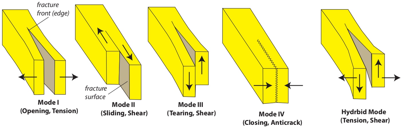
Various ‘modes’ of fractures depending on the relative movement of fracture surfaces. (Source: Rasoul Sorkhabi)
Mode I fractures are tensile (opening) fractures in which two fracture surfaces move away from each other. Joints are basically Mode I fractures. In contrast, shear fractures involve the relative movement of rock blocks parallel to the fracture surface. Shear fractures may have lengths at the scale of millimeters (microscopic) (called microfaults) or at the scale of centimeters (minor faults); large (meter-length) shear fractures are properly called faults. Shear fractures include Mode II or sliding fractures, in which the relative movement is perpendicular to the fracture front (as in strike-slip faults), and Mode III or tearing mode, in which the relative movement is parallel to the fracture front (as in dip-slip faults). Hybrid fractures combine both tension (Mode I) and shear (Mode II or III) movements. Mode IV or closing fractures are mineral-scale anti-cracks; stylolites (pressure solutions) are typical examples of this mode.
Stress: Principal, Normal and Shear
Stress (σ) and pressure (P) are both defined as force (F) per unit area (A), and have the unit of pascal. One pascal (Pa) is one newton per square meter (or 1 kg cm-1 s-2); 100,000 pascal is equal to one bar or 0.98 atmospheres of pressure; one megapascal (MPa or 106 Pa) equals 10 bars and one gigapascal (GPa or 109 Pa) equals 10 kilobars. One bar is 14.503 pounds per square inch (psi) and one psi is 6895 Pa.
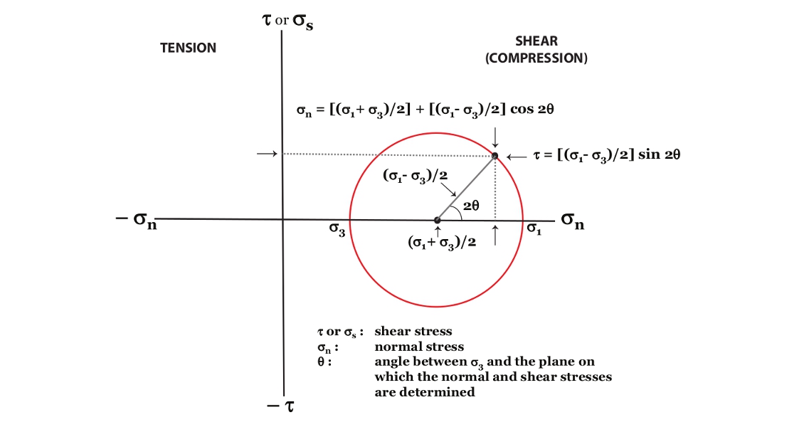
Mohr circle and calculations of normal stress and shear stress on a plane. (Source: Rasoul Sorkhabi)
Stress differs from pressure in that it also includes a sense of directionality (vertical or horizontal); in other words, stress is a vector quantity while pressure is a scalar quantity. Pressure (P) at a given depth is given ρgz where ρ is density of the material (rock or fluid), g is gravitational acceleration (9.8 m/s2) and z is the target depth.
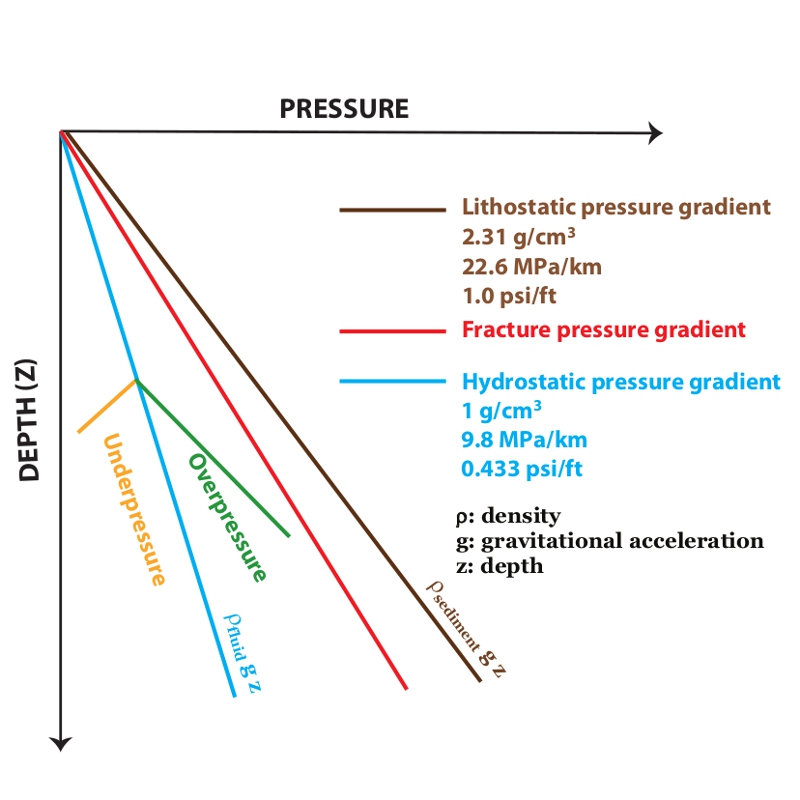 Calculations of subsurface pressures for fluid (water) and sedimentary rocks based on their pressure gradients. Fracture pressure is the stress sufficient to fracture a rock. It is related to pore fluid overpressure. Fracture pressure gradient is usually 18-20 MPa/km. Fracture pressure can be determined from leak-off tests. (Source: Rasoul Sorkhabi)In his 1942 book The Dynamics of Faulting and Dyke Formation with Application to Britain, the Scottish geologist Ernest Masson Anderson (1877–1960) formulated the stress field of a three-dimensional rock body in terms of three principal stress axes – maximum or greatest (σ1), intermediate (σ2), and minimum or least (σ3). All these stresses acting upon a rock body are compressional but may have different magnitude and direction. In normal faults, σ1 (rock overburden) is vertical and extension takes place in the direction of σ3. In reverse (thrust) faults σ1 is horizontal and σ3 is vertical, and thrust shortening takes place in the direction of σ1. In strike-slip faults, σ2 is vertical while both σ1 and σ3 are horizontal, and slip occurs at an angle of 45° or less to the orientation of σ1. Mean stress is the arithmetic average of the three principal stresses (σ1 + σ2 + σ3 divided by 3). (For more information refer to ‘Know Your Faults, Part I‘ and ‘Know Your Faults, Part II’, GEO ExPro, Vol. 9, No’s. 5 and 6.)
Isotropic (uniform) stress or confining pressure is a situation in which a body is compressed by equal pressure in all directions; it may be lithostatic stress (a subsurface point under the weight of a rock overburden) or hydrostatic stress (a point enclosed by water). (Note that in some scientific literature, hydrostatic pressure and confining pressure are used as synonyms). Often, however, tectonic forces alter confining pressures; therefore, stress is not equal in all directions. Deviatoric stress is measured as total stress minus mean stress acting upon the rock body. Differential stress is measured as σ1 – σ3. If differential stress exceeds the strength of the rock, the rock deforms (and eventually ruptures). Differential stress may be compressional, tensional, or shear, which also determines how the rock deforms in response to the stress.
Compression is the stress that shortens (squeezes) a rock body; tension elongates (stretches) the rock body in two opposite directions. Normal stress (σn) acts perpendicular to a rock surface; it may be compressional (positive) or tensile (negative). Effective normal stress is normal stress minus pore fluid pressure. Shear stress (σs or τ) acts parallel to the rock surface and causes two rock units to slide over each other; in other words, shear stress changes the angles in a rock body.
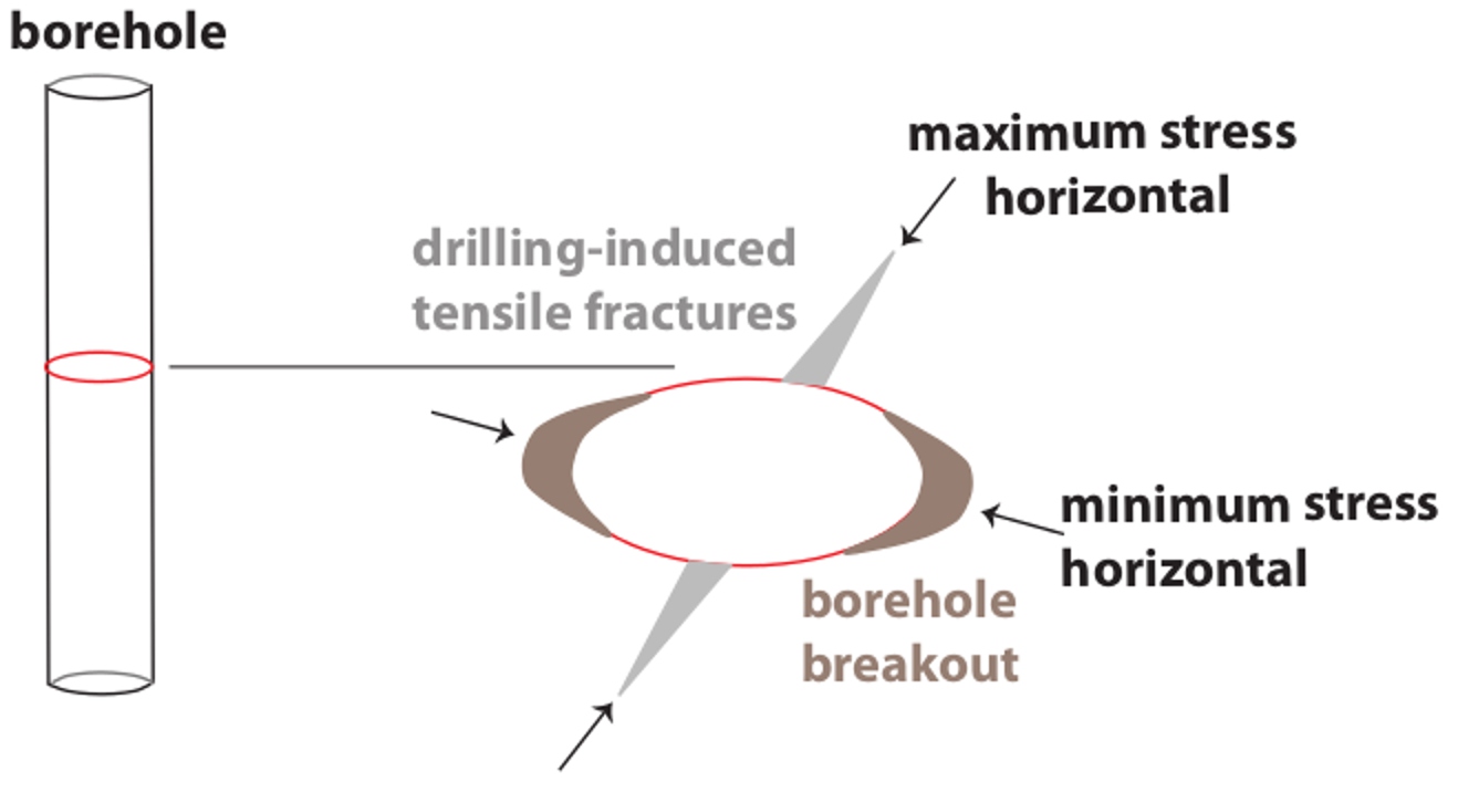
Horizontal stresses in a borehole related to borehole breakout and drillinginduced tensile fractures. (Source: Rasoul Sorkhabi)
Geologists also distinguish between paleostress (stress that acted upon rocks in a given area in the geological past) and in-situ or contemporary stress, which can be inferred from plate motions, earthquakes or borehole data.
Mohr Envelope and Coulomb Failure
We are now in a better position to delve more into geomechanics and study how rocks fail and fracture under stress. We owe this analytical knowledge largely to a group of French physicists and scientists: Guillaume Amontons (1663–1705), Charles-Augustin de Coulomb (1736– 1806), Claude-Louis Navier (1785–1836) and L. Hartmann, as well as the German engineer Christian Otto Mohr (1835– 1918), European engineer Richard Edler von Mises (1883–1953), English engineer Alan Arnold Griffith (1893–1963), and Austrian soil engineer Karl von Terzaghi (1883–1963). These scientists developed powerful mathematical diagrams and equations that calculate and thus predict the development of rock fractures in relation to stresses applied to rocks.
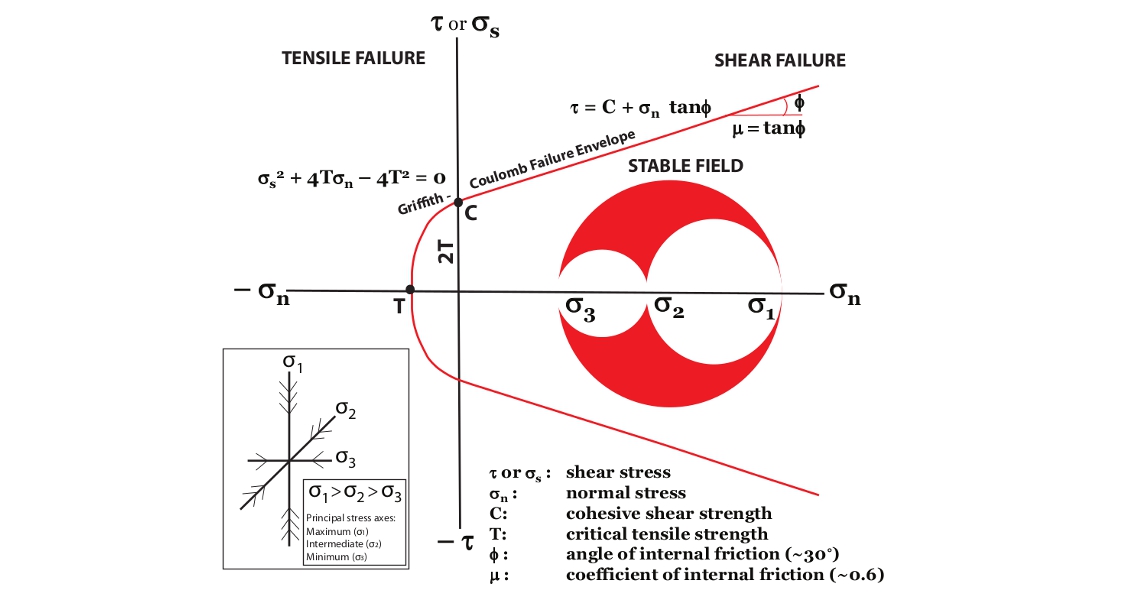
Mohr envelop of failure using Griffith-Coulomb criteria. Depending on the position of the Mohr’s circle of stresses, there are three fields: Stable (below the failure envelope), critically-stressed (touching the failure envelope), and unstable (beyond the failure envelope in which the rock may fracture by tension or by shear). Three principal stress axes are also depicted. (Source: Rasoul Sorkhabi)
Graphical representation of rock failure or fracture, called Mohr diagram, includes the relationship between shear stress (σs or τ) on the vertical axis and normal stress (σn) on the horizontal axis of the diagram, and the distance of rock stress (represented by a circle) from a line called the Mohr envelope of failure. Various scientists have attempted to quantify the criteria when the stressed rock exceeds the failure envelope and thus fractures either by tension or by shear. In 1699, Guillaume Amontons suggested that the shear force parallel to a rock surface necessary to initiate slip in the rock is directly proportional to the normal force acting upon the surface. The proportionality constant μ is called the coefficient of internal friction (a term introduced by Navier in 1833). Therefore, we can write:
τ = μ σn
For solid rocks, the value of μ ranges from 0.47 to 0.7; for general calculations it is assumed to be 0.6.
In 1773, Charles Coulomb verified and refined Amontons’ equation. He recognized that a rock fractures only if the cohesive strength (C) of the rock is exceeded. In other words:
τ = C + μ σn
The constant C represents the critical shear strength of the rock (or resistance of the rock to shear stress) when normal stress is zero. Rocks also have a critical tensile strength, plotted as the point T, on the Mohr diagram. Cohesive strength of a rock is twice its tensile strength (C = 2T).
Further work by Navier and Mohr in the 19th century advanced our understanding of rock failure. The following equation quantifies the line of shear failure on Mohr diagram and is called Coulomb-Navier, Coulomb-Mohr or simply Coulomb criterion of failure:
τ = C + σn tanφ
where φ is the angle of internal friction (about 30° for sand grains).
The Mohr diagram indicates that as the normal stress increases we also need more shear stress to fracture the rock.
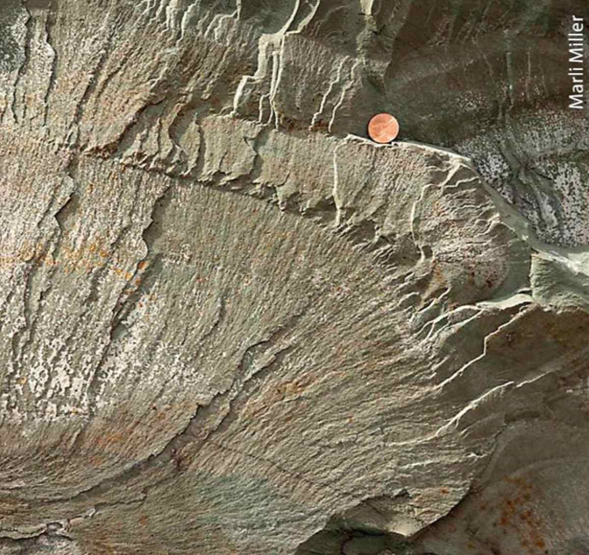 Plumose fracture in argillite, Proterozoic Appekkuny Formation, Montana. Fracture surfaces often display plume-like features; the axis of the plume indicates the direction of fracture propagation (parallel to σ1). The fracture probably originates from a heterogeneity in the rock (such as inclusions and sedimentary structures). The average velocity of fracture propagation has been measured to be half the speed of sound waves. The presence of plumose features suggest that the fracture is still in open (tensile) mode. (Source: Marli Miller)The Coulomb criterion describes failure of rocks by shear (the right side of Mohr diagram), but is not applicable to tensile fracturing (left side of the diagram). Experimental work has shown that the Mohr envelope for tensile failure is shaped like a parabola, and the point T (critical tensile strength of a rock) represents the intersection of Mohr envelope and the horizontal axis (normal stress). The value of T varies for rocks. In 1920, Alan Griffith noted that this variation is due to the existence of microscopic cracks, flaws, grain boundaries and pore spaces in rocks; these random, pre-existing features, from which tensile fractures originate, are collectively called Griffith cracks. When a Griffith crack is oriented perpendicular to tensile stress, the crack easily propagates at its ends in a direction perpendicular to σ3, the minimum principal axis. When the crack is oriented perpendicular to a compressive stress, it tends to remain closed. Griffith criterion for tensile failure on the Mohr envelope is:
σs2 + 4Tσn – 4T2 = 0
In summary, a combined Griffith-Coulomb criterion is the best available model for quantifying the fracturing of rocks by tension or shear. In ductile regimes, where the Mohr envelope is expected to flatten and a maximum shear stress is reached, other formulations such as Von Mises criterion should be used to describe rock deformation.