Part I
The term ‘fracture’ includes any break or structural discontinuity in rocks in which two rock fracture surfaces (usually planar) are separated by a narrow slit, far shorter than the length or height of the fracture. Fracturing happens because of the loss of cohesion in the rock and is a typical expression of brittle deformation in the Earth’s upper crust (in contrast to the flow and folding structures which occur at crustal depths under ductile conditions).
 Rock climber using natural fractures in Cornish granite as hand and foot holds. (Source: Jane Whaley)Fractures are the most common structural features that are found in all types of rocks (igneous, sedimentary and metamorphic) and in all plate-tectonic settings, from continental rifts and mid-ocean ridges to subduction trenches and continental collisions. Knowledge of fractures is important for scientific, technological as well as economic purposes. Fractures are essential parts of the geological processes that form mountain belts, sedimentary basins, coastlines, ocean floors, earthquakes, and so on. Fractures also provide fluid pathways for the movement of groundwater, oil and gas, ore deposits, and magma.
Scientific investigations of fractures date back to the nineteenth century and have grown rapidly in recent decades. These investigations include rock observations and structural mapping at micro and macro levels, experimental and analogue works, geometrical and geomechanical analysis, and numerical modelling and simulation.
In petroleum field operations, we often distinguish between natural (naturally occurring) fractures and those of drilling-induced and hydraulic (induced by fluid injection for fracturing rocks) origin. Even though natural fractures are found in all rocks, they are not all the same, and the simple term of ‘natural fractures’ does not do justice to their complexities. Characterisation of fractures based on scientific principles and data is thus crucial for their utilisation in resource exploration and production.
Fractures Come in Various Forms
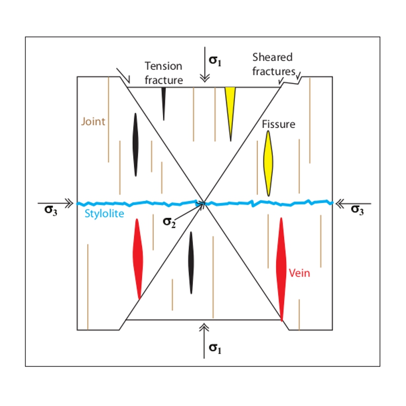 Various types of fracture on a conjugate normal fault structure. Modified from Haakon Fossen, Structural Geology (2010).Fracturing occurs at various scales from mineral to tectonic plate, and is generated in numerous forms by a number of distinct processes. Fracture is a collective term for a variety of breaks in rocks.
On a mineral grain scale, fracture is crystal breakage along uneven or curved surfaces; it requires external force applied to the crystal. (Fracture is different from crystal cleavage, the tendency of the mineral crystal to split along one or more smooth planes, which is related to the arrangement of chemical bonding in the mineral lattice.) On a thin-section of rock specimen, we can observe micro-fractures which may be intragranular (restricted to individual grains) or intergranular (cutting across several grains).
In outcrops of sedimentary rocks, bedding planes and joints are probably the most eye-catching rock fractures. Bedding planes separate layers of successive sedimentary rocks due to changes in lithology or other sedimentary properties. The term joint was first used by miners who thought that the rocks were ‘joined’ along these planes like building blocks. Joints do not show visible shearing but are dilational (opening) or extension fractures formed by tensile stress. Other types of extension fractures include fissures (wide openings filled with air, water or other fluids), veins (mineral-filled), and dykes (vertical, wide fractures filled with plutonic or volcanic rock).
Sheared fractures, on the other hand, show relative movement (slip) of two fracture walls parallel to the fracture plane (slip surface). Sheared fractures usually have displacements of millimetre to centimetre scale, while faults have larger displacements. Faults often have polished or striated surfaces (called slickensides) that result from frictional sliding of fault walls. Geologists can use slickenlines (grooves on the fault surface) to determine the direction of faulting.
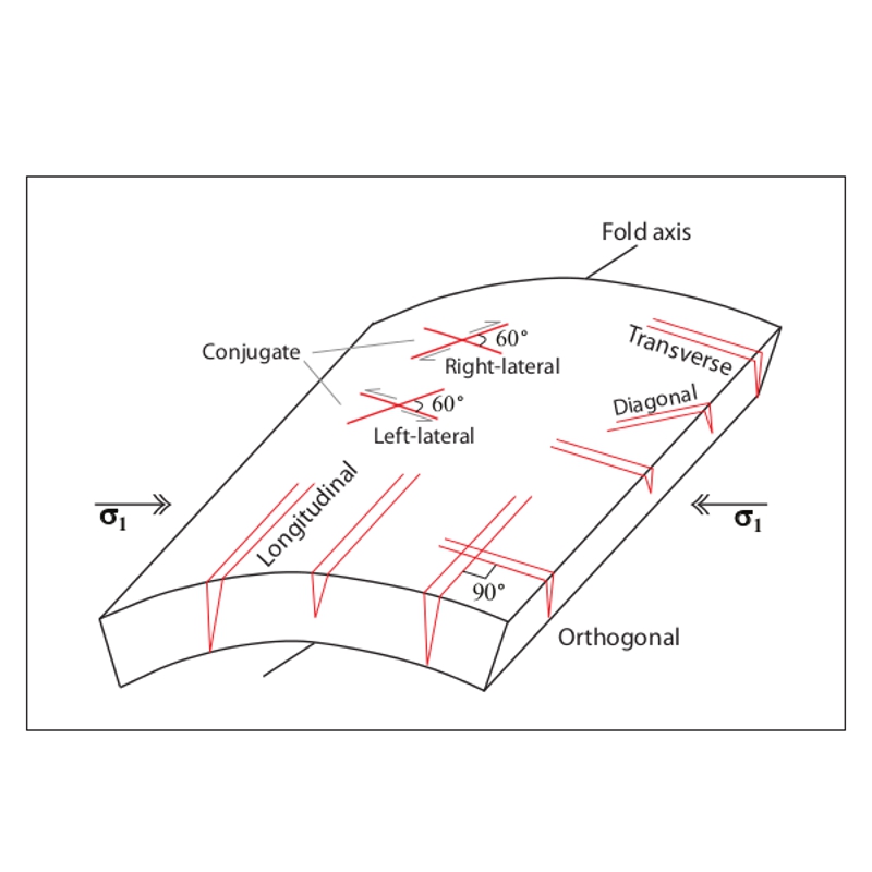 A geometric classification of fractures into longitudinal, transverse (cross), conjugate, diagonal (oblique), and orthogonal fractures developed on a fold structure. These field-based concepts were formulated by geologists in the first half of the 20th century. Modified from Singhal and Gupta, Applied Hydrogeology of Fractured Rocks (2010).In the petroleum and groundwater industries, fracture often refers to reservoir-scale joints and other open, extension fractures that have positive implications for subsurface fluid flow. In this limited sense, large faults, for example, are regarded as a different feature. Thus we often hear about ‘fractures and faults’ in reservoir rocks, which is like saying there are ‘animals and dogs on our farm’. Faults indeed represent a significant type of fracturing and are genetically associated with many other types of fractures. (For various types of faults, see the two-part article ‘Know Your Faults’, GEO ExPro, Vol. 9, No. 5 and No. 6).
Some special types of fractures are also noteworthy here. Mud cracks (desiccation fractures) are polygons of extensional fractures that develop in highly clay-rich sediments due to shrinkage and loss of water. Cleats are natural, open-mode fractures in coal beds filled with natural gas or water. Deformation bands are millimetre-wide, planar features in high-porosity sandstones that show little offset but are characterised by low-porosity, low-permeability bands rocks but they are not all the same due to mineral grain flow, fracturing or cementation; they cluster around faults.
Some fractures form spectacular features on satellite images; they are also important for fluid movements on a crustal scale. Lineaments are physiographic lines on a regional extent that indicate deformation of rocks by major faulting or folding. Ocean-floor fracture zones extend beyond the mid-ocean ridges to continental margins.
Fracture Characterisation
A comprehensive fracture characterisation involves mapping, measuring and documenting a number of parameters including the following:
1. Type of fracture and its infilling (whether open or filled).
2. Association of fracture with particular lithology, structure (fault, fold or no structure), deformation history (age), and present (in-situ) stress field.
3. Systematic rock fractures often develop in one or more fracture sets. It is important to map and quantify these fracture sets and work out their relative ages.
4. Attitude of fractures include strike (with respect to North) and dip angle (from 0° horizontal to 90° vertical) and direction (dip direction is always perpendicular to strike direction). These data can be displayed on stereographic equal-area plots. Fracture strike trends can also be plotted on a rose diagram or a histogram.
5. Fracture length indicates the lateral persistence of the structure. Trace lengths of <1m are very low persistence, while those of >20m are very high persistence fractures.
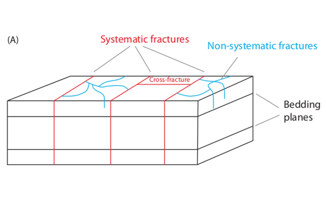
In 1961 AAPG Bulletin (Vol. 45), R.A. Hodgson published his studies of joint patterns developed on rocks in Arizona and Utah, in which he distinguished between systematic joints, which are planar, parallel and evenly spaced, and non-systematic joints, which are irregular in their form, orientation and spacing. Systematic joints form ‘pervasive fracture sets’ perpendicular to bedding surfaces and may be linked by ‘cross-joints’. Fracture sets may intersect at a constant dihedral angle; conjugate fractures have dihedral angles of 30°–60°, while orthogonal fractures are at right angles (nearly 90°). Non-systematic joints are curved and often terminate at bedding surfaces.

Bedding joints Based on the orientation of fractures with respect to bedding fractures (notably joints) are classified into strike joints (in plan view, parallel to the strike of bedding plane), dip joints (perpendicular to bedding), and bedding joints (parallel to bedding in both plan and vertical view).
6. Spacing of fractures and its relation to bed thickness or structural position (fault-related, fold-related, or none) are crucial data. At outcrops, fracture spacing can be measured by a tape along a scanline. Observations show that very stiff layers have more joints than very weak layers; and for a given lithology, thinner beds have closely-spaced joints. The International Society for Rock Mechanics (ISRM) has recommended the following scale for classifying fracture spacing: extremely close spacing (<0.02m), very close spacing (0.02–0.06m), close spacing (0.06–0.2m), moderate spacing (0.2–0.6m), wide spacing (0.6–2.0m), very wide spacing (2.0–6.0m), and extremely wide spacing (>6.0m). Fracture frequency is defined as the number of fractures per metre length. It is thus the inverse of fracture spacing. Fracture frequency is equal to 1/fracture spacing.
7. Population: The occurrence of fractures can be quantified in 1D (fracture frequency for a given length), 2D (fracture intensity for a given area), and 3D (fracture density for a given volume).
8. Aperture is the perpendicular distance between the adjacent rock walls (fracture surfaces) of a fracture. It may be open (containing air, water or other fluid) or closed (infilled by fault rock or some other injected material). Aperture may be tight (<0.25mm) for closed fractures or wide (>10mm) for open fractures. Aperture decreases along the length of a fracture toward the fracture front. Aperture may also change along the height of a fracture due to asperities (see below). Often the terms ‘equivalent’, ‘hydraulic’, and ‘mechanical’ apertures are used depending on the methods and purpose of their estimation.
9. Fracture walls do not have perfect parallel, smooth surfaces but contain roughness and irregularities called asperities, which reduce fracture permeability. Some knowledge of asperities may thus help better modelling of fluid flow through the fracture.
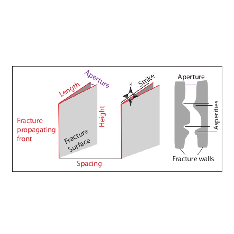 Anatomy of rock fractures. (Source: Rasoul Sorkhabi)10. Fracture stiffness (measured in Pascal/mm) describes the stress-deformation of the fracture with respect to normal stress (normal stiffness or resistance to closure) and shear stress (shear stiffness or resistance to shear displacement). Data on fracture stiffness are hardest to obtain because they involve geomechanical laboratory or in-situ experiments of fractured rocks.
11. Fracture connectivity: intersection of natural fractures provides a permeability network for fluids, whereas disconnected, isolated fractures are not hydraulically effective. The chance of fracture connectivity increases with larger population and lengths of fractures in a given rock volume.
12. Petrophysical properties of fractures including porosity and permeability.
Fractured Reservoirs
All reservoir rocks are fractured to some degree and usually by more than one process. Nevertheless, the term ‘fractured reservoir’ refers to a tight reservoir (matrix permeability < 0.1 mD) in which natural fractures play a significant permeability role for fluid flow (water, oil or natural gas). In these reservoirs, therefore, the mapping and characterisation of fractures in a 3D geological model and the quantification of the petrophyscial properties of fractures is of paramount importance for drilling and production.
In his book Geologic Analysis of Fractured Reservoirs, Ronald Nelson has described a classification of reservoirs based on the porosity and permeability of both rock matrix and fractures. Four types are thus distinguished:
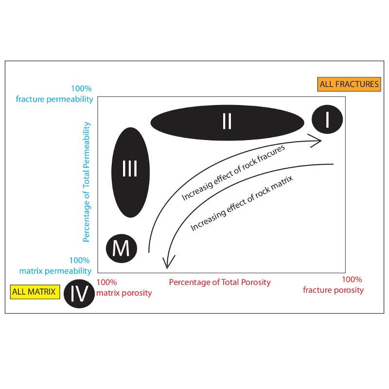 Classification of reservoirs based on petrophysical properties of rock fractures. Modified from Ronald Nelson, Geologic Analysis of Fractured Reservoirs (2001).• In Type I reservoirs, fractures provide the essential porosity and permeability (e.g. Amal field, Libya; Ellenburger fields, Texas). These reservoirs have high declining curves per well.
• In Type II reservoirs, fractures provide the essential permeability (e.g. Agha Jari field, Iran; Rangely, Colorado).
• In Type III reservoirs, fractures contribute to the permeability of an already producible reservoir (e.g. Kirkuk, Iraq; Cottonwood Creek, Wyoming).
• In Type IV reservoirs, fractures actually act as fluid barriers (e.g. Beaver Creek, Wyoming; Houghton, Kansas). These reservoirs are structurally compartmentalised.
Subsurface fractures always pose a challenge to exploration and production. In the petroleum, geothermal and groundwater industries, therefore, a wide variety of materials, tools and techniques are utilised to identify, map and characterise fractures. These include basin tectonics, outcrop analogues, cores, borehole imaging logs, seismic sections, in-situ stress data, well flow tests, geomechanical experiments, and so forth.
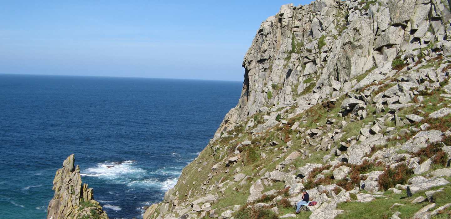 Fractured granite in Cornwall, UK. (Source: Jane Whaley)