“When developing an oil field or, for that matter, any subsurface resource, geoscientists see only a small fraction of what is actually there through bore hole data,” says Christopher Zahm, a research associate at the Bureau of Economic Geology (BEG), University of Texas at Austin. “From this limited data, they determine what rock features will impact the extraction of those resources. Outcrops provide an analogue the geoscientist can use right at the outset of a project for predicting what can be expected underground.”
A digital outcrop model (DOM) is a digital, 3D representation of an outcrop surface. These models enhance conventional fieldwork, particularly in areas that are difficult or dangerous to access. The geological interpretation can be performed on a computer screen. The interpreter can use the models to accurately measure different geological features such as the spatial distribution of rock types, fracture orientation and density, layer thicknesses, and surface orientations. The accuracy of the interpretation and identifiable geological features is highly dependent on the outcrop model resolution, but is generally known to within 25cm or less.
The use of commercial unmanned aerial vehicles (UAVs), when coupled with photogrammetry, provide a unique opportunity for improved DOM development. This method is relatively inexpensive and, when used in combination with differential GPS, the end results are very precise, and informative outcrop models can be developed with minimal effort.
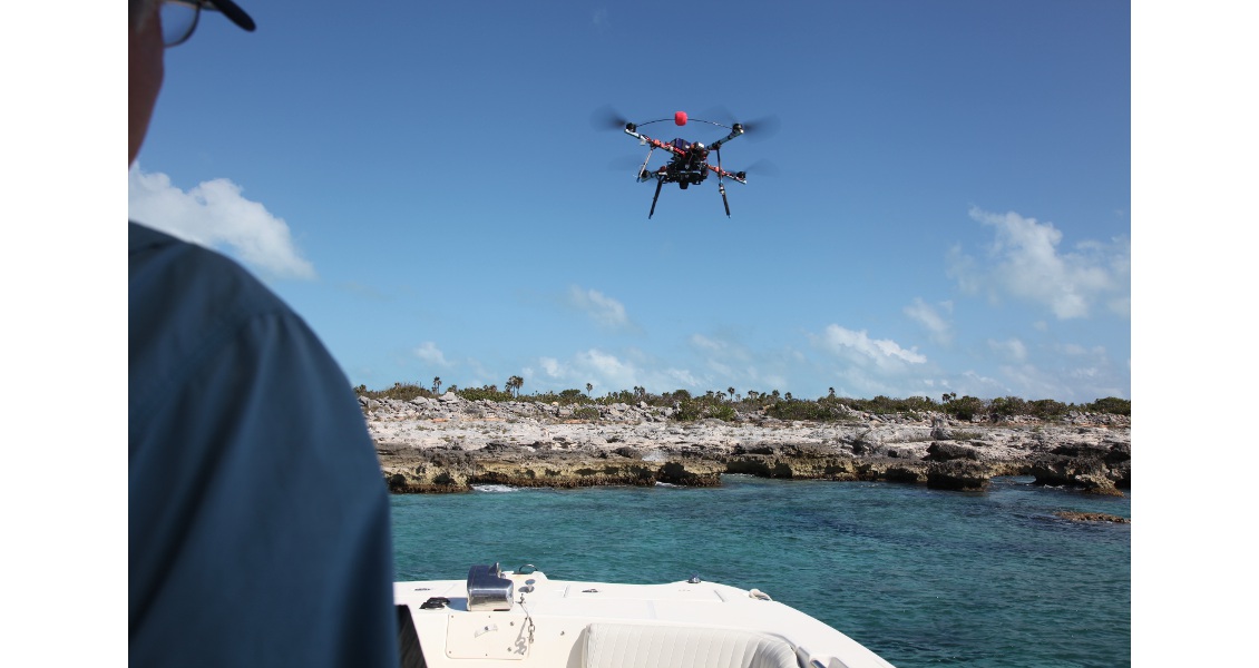
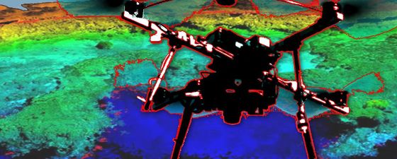
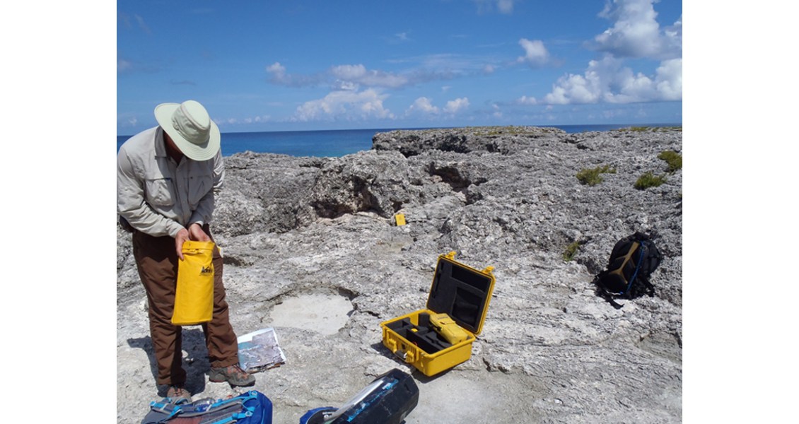
Drone surveying on West Caicos, Turks and Caicos Islands, BWI. (Source: Christopher Zahm, BEG)
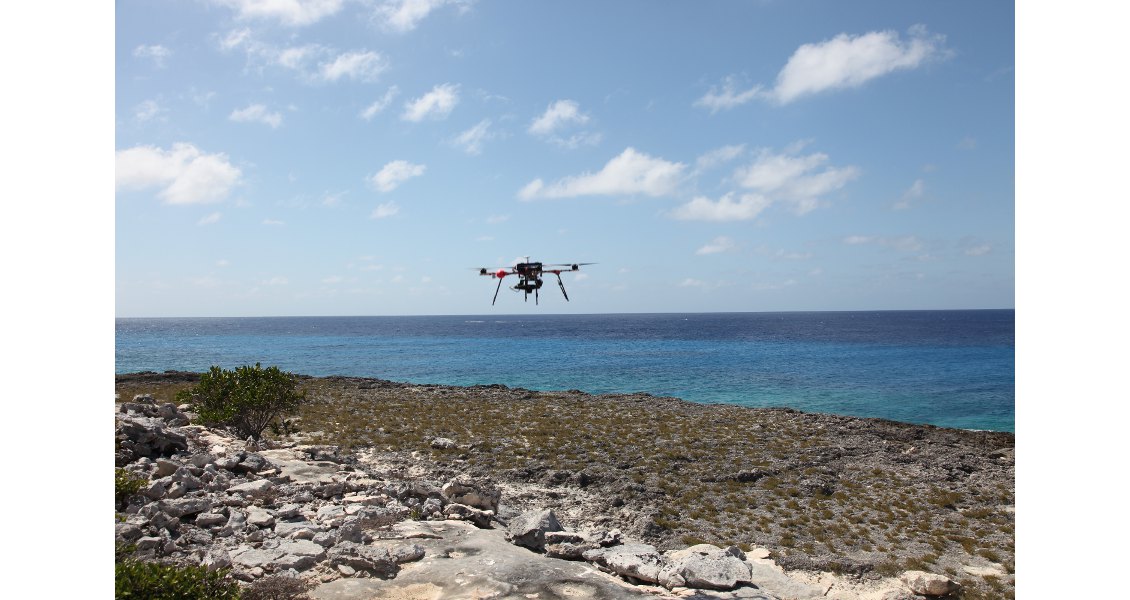
Drone surveying on West Caicos, Turks and Caicos Islands, BWI. (Source: Christopher Zahm, BEG)
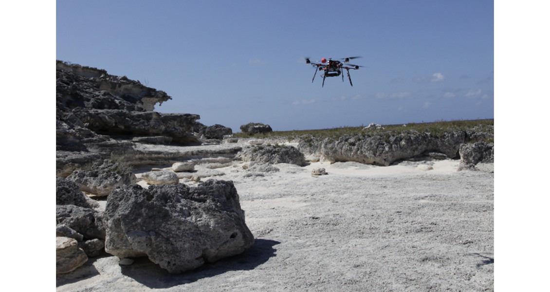
Drone surveying on West Caicos, Turks and Caicos Islands, BWI. (Source: Christopher Zahm, BEG)
“The process of drone acquisition can be broken down into four major steps,” says Josh Lambert, a research scientist associate at the BEG. “Those four steps are acquisition, development, exportation, and finally, interpretation.” Josh explains these steps below.
Acquiring, Developing and Exporting Data
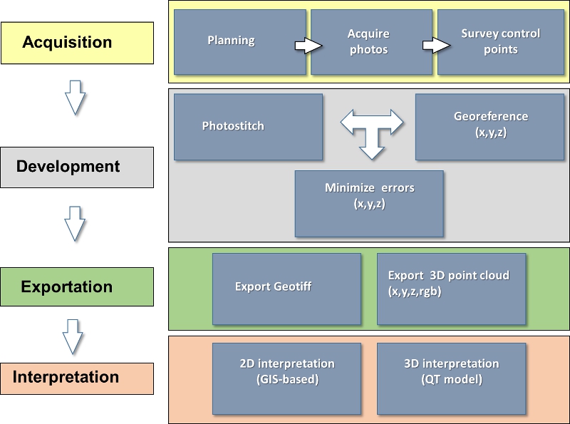 Simplified photogrammetry workflow. (Source: BEG)“The acquisition process includes pre-photo shoot planning, the actual photo shoot, and surveying of control points. Acquisition planning is accomplished in person during fieldwork or through interpreting Google Earth or other satellite imagery. This allows for the delineation of an acquisition area and also gives an idea of the time it would take to shoot.
Surveying-in control points consists of getting some form of GPS data from either features or markers that are placed on the ground. Ideally, this GPS data is collected with a highly accurate (centimetre resolution) real-time kinematic GPS and base station, although data could be collected with less accurate results with some form of handheld GPS if need be. We use ground markers to act as targets that we can see easily on photographs (see photos below) and then input GPS data (latitude, longitude, altitude) to have a geographic reference for the photograph. We then fly a drone over the area and collect photographs in a roughly equal interval based on either time (one photograph every few seconds) or on the distance that the drone travels (one photograph every few metres). Depending upon the area that is being surveyed this could result in hundreds, if not thousands, of images. The goal here is to have a series of photographs that are overlapping. The more overlap the better, aiming for 60% is a fair assessment.”
The development aspect involves pumping the GPS and the photographs into photogrammetry software. “The photogrammetry software that we use is Agisoft Photoscan Professional,” Josh continues, “however, there are other good photogrammetry software packages out there. The software processes photographs under the assumption that they are each taken from a different perspective and that the images are overlapping. It also finds the position of the camera used for each image and takes into consideration the camera calibration parameters (shape of lens, etc.) This image alignment process can be optionally constrained with the use of GPS data.
Setting up real time kinematic base station for GPS. (Source: BEG)
Example of control point used for surveying. (Source: BEG)
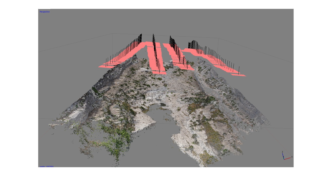
Example of flightpath and model displayed in photogrammetry software: Agisoft Photoscan Pro. The pink squares represent the location of the camera, or UAV, during photo acquisition. (Source: BEG)
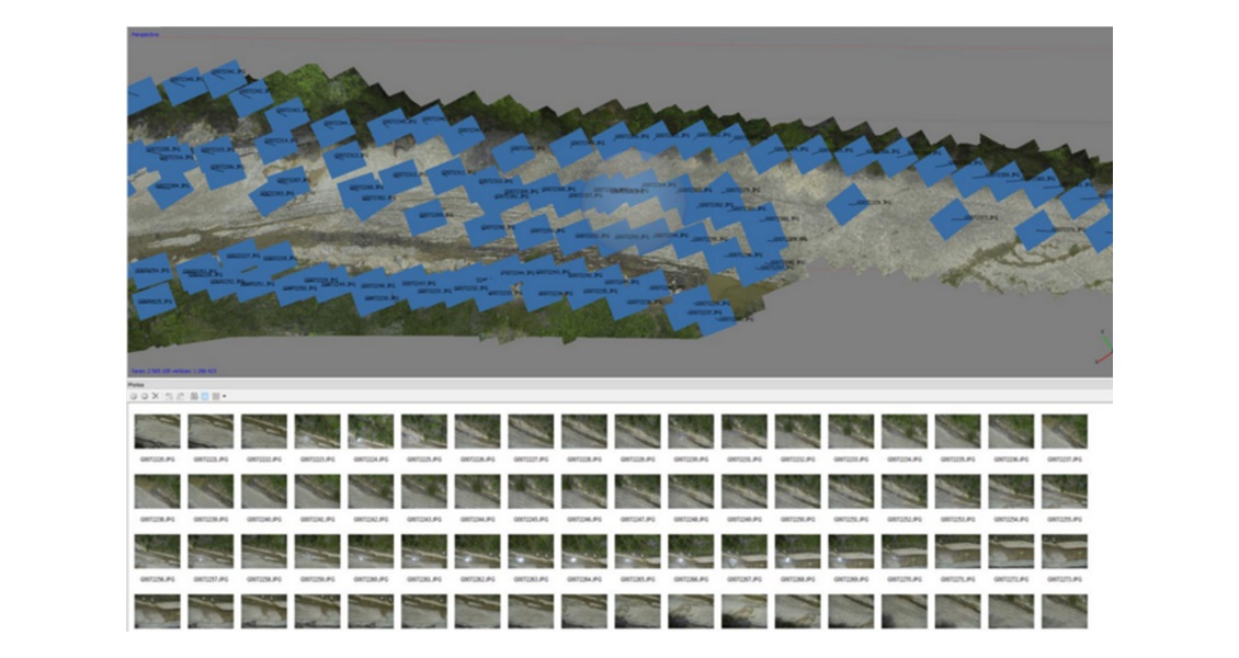
Photostitch. Screen snapshot of an aligned flight and photogrammetry model inside of Agisoft Photoscan Pro. (Source: BEG)
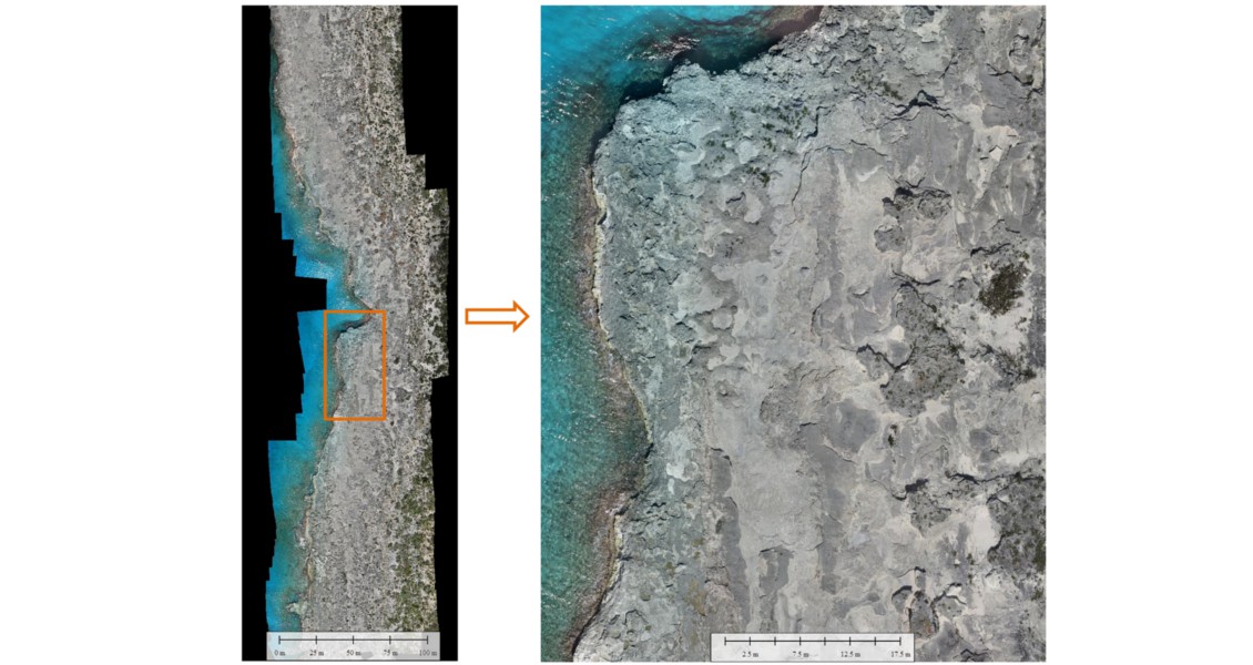
UAV Acquired Image (camera: Sony NEX7). Acquired at 20 meters, over 300 individual images (left) are used to create the zoomed-in detail (right). (Source: BEG)
“Part of the development process is the insertion of GPS data into the photographs. I would say 10 ground control points would be an adequate starting point for providing GPS data over a survey area. This process simply means going through photographs, finding a location where you know the latitude, longitude and altitude (hence the ground control marker) and inputting that data into the photograph. For example, over a survey area that has 500 pictures, you might have 10 ground control markers, which might be represented on 50 or so (~10%) of the images. Having this GPS data allows either the GeoTIFF, point cloud, or digital elevation model to be exported into a visualisation tool or a geographic information system (GIS) software package and be able to drop into a coordinate system so measurements can be made. The software that we use estimates errors in metres so at times it can be easy to follow up if a point is causing problems with a particular model.
“The exportation step is rather simple: just exporting the model into whatever format that would best suit the users’ needs. The GeoTIFF works great for a planar type exposure as it is just an image file (tif) with GPS inputs so it can be projected into a coordinate system. Digital elevation models can also be created through the photogrammetry process for spatial analysis and 3D representations of the area.”
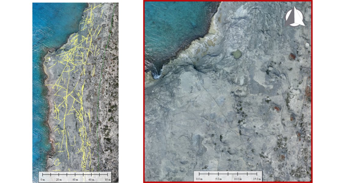
Interpretation: 2D. UAV acquired photographs used to map fracture intensity. (Source: BEG)
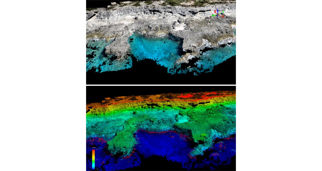
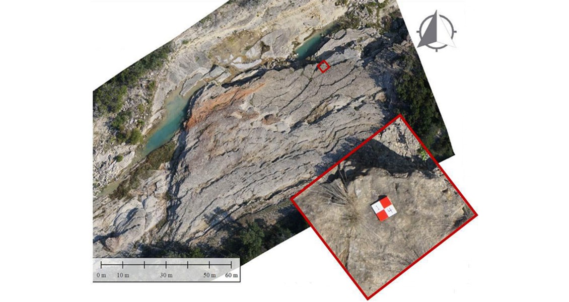
Interpretation: 3D. UAV-acquired orthophotographs enable facies mapping and quantification of the spur and groove geometry at the South Reef locality, West Caicos, British West Indies. This image is a point cloud that is depicting an oblique angle over the outcrop. The lower image shows elevation, blue being the lowest altitude with red being the highest represented in the model. Surface field mapping is plugged into these 3D elevation models to create a 3D analogue that can be applied to understanding similar formations in the subsurface. (Source: BEG)
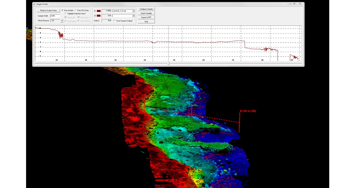
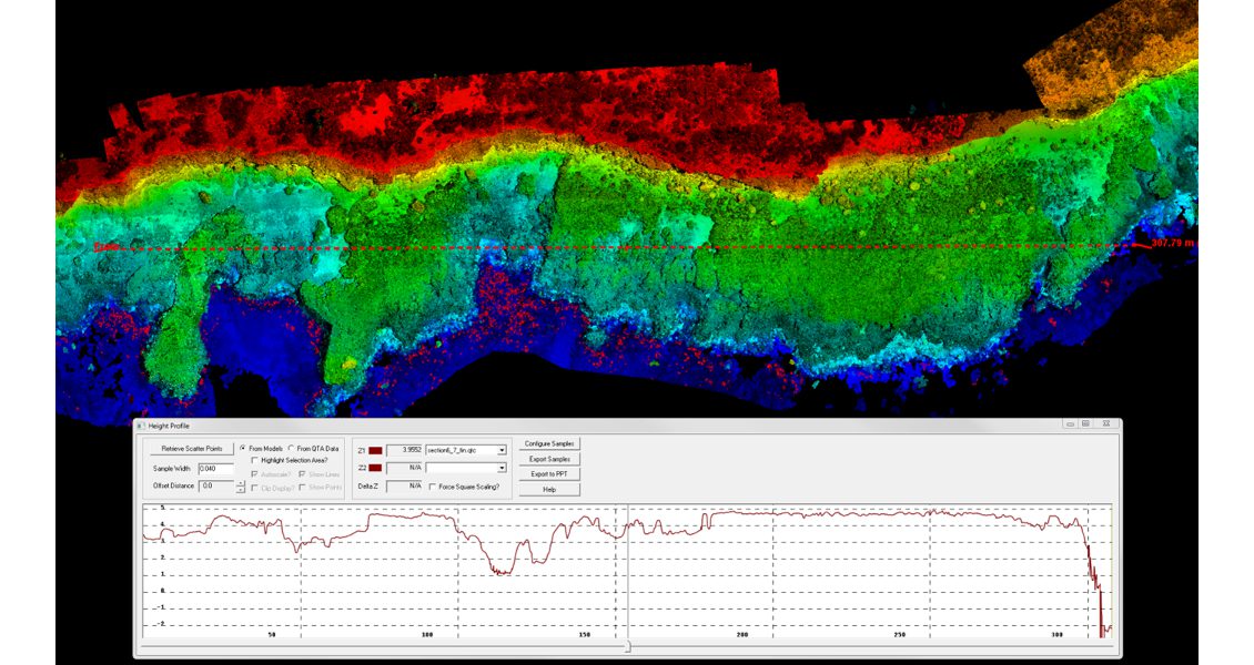
Interpretation: 3D. Quantitative analysis of elevation profile, West Caicos. (Source: BEG)
Interpretation: 3D. Quantitative geometric constraints, West Caicos. (Source: BEG)
Interpretation is the Star
“All this data is well and good but the analysis and interpretation being drawn from these models are the real stars of the show,” says Josh. “The interpretation of these 2D images and 3D outcrop models give us a perspective that can’t be understood merely by conducting fieldwork on foot and at a scale that can’t always be captured by aerial or satellite photography. These outcrop models provide a great utility for reference and for analysis in geographic information systems. Geoscientists determine orientation, distribution and frequency of fractures as well as the slope or dip of outcrops from the model products. Specific rock characteristics or facies can be mapped on these products to aid in understanding the geologic settings and stratigraphy. Measurements can be conducted to determine lengths or the areas of exposures as well as volumetric information in regard to channels or other geologic features. Statistics can also be applied to the model to determine and quantify trends in the geology that are exhibited on the images.”
Chris Zahm explains it this way: “The process of georegistered photogrammetry allows for two different types of data – high resolution geotiffs (2D) and 3D point clouds where points spaced millimetres apart are referenced with real-world X,Y,Z locations and contain colour information (RGB). GeoTIFFs are useful for mapping key geologic contacts such as facies boundaries, faults, fractures and unconformities. The geoTIFFs are imported into a GIS-based software (e.g., ARC or Global Mapper) where the lines can be drawn for the geologic feature of interest. After the interpretation is complete, data and statistics about the features can be queried; for example, the orientation and length of a fracture or the area of an exposed facies.
A more complex interpretation is performed when the photogrammetry data is exported to the 3D environment. In this case, geologic interpretations are queried for volumetric analyses and an exposure can be coloured by the interpretation to provide the interpreters or others with insight into what is interesting or useful within the 3D data.”
Canyon Dam, Texas. Short movie of point-cloud rendered in 3-D, displayed in QT Modeler. (Source: BEG)
Understanding Geospatial Relationships
An excellent example of how this process can help the geoscientist understand geospatial relationships, and better understand what is happening in the subsurface, comes from the BEG’s work on a 7.5 km exposure along the western coast of West Caicos, British West Indies. The area displays well preserved depositional facies and extensive early fracture development in this Pleistocene carbonate strata.
“UAVs and real-time kinematic GPS were used to generate an integrated map and 3D model of fractures within a framework of depositional facies,” says Chris. “The results from this study have demonstrated a critical link between facies and fracture style, intensity, and orientation. Early formed fractures occur in both the margin parallel and perpendicular to the direction and the longest features developed in the grainstone facies. In addition, fracture systems play a fundamental role in the orientation of easily identified spur and groove systems preserved in the outcrop exposure.”
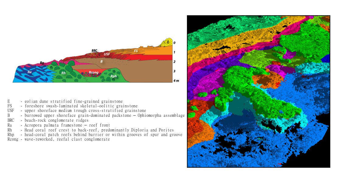
Interpretation: 3D. Mapping of facies from 3D model, West Caicos. (Source: BEG)
“The mobility the UAV provides allows us to get a better perspective of the areas that we are surveying by positioning the camera to take pictures at different vantage points. The software puts it all together to make the models, which ties back to the broader goal of understanding reservoir environments and using outcrops as analogues for the subsurface,” concludes Josh.