A natural metaphor for seismic imaging is the echo-location applied by toothed whales, some birds and, most famously, by bats. These flying mammals have been able to occupy their nocturnal ecological niche by using echo-location, the most sophisticated acoustic imaging method in nature.
How bats process sound
 Photo: CGGVeritasAs with seismic acquisition systems, the bat is equipped with its own source, i.e. the rapid succession of calls it emits from its open mouth, which appear as clicks to humans. For most bat species each call is a broad-band signal that sweeps through frequencies from 14 kHz to well over 100 kHz. As a comparison, audible ranges for humans are 20 Hz to 20 kHz. The duration of a call is anywhere from 0.2 to 100 milliseconds. After the call, the bat has to stay quiet for a while, listening for the echo of the call, which is then processed in real time, creating a mental image of the surroundings in the bat’s brain.
The listening time (i.e. the time between the calls) will determine the range of the echo-location of the bat; the longer the listening time, the farther it can “see”. For example, a call interval of 100 ms (typical for a bat searching for insects) allows sound to travel in air roughly 34m, so a bat can only detect objects as far away as 17m, as the sound has to travel out and back. With a call interval of 5 ms in the final moments as it closes in on its prey, the bat can only detect objects up to 85 cm away. Therefore, the bat constantly has to make a choice between getting new information updated quickly and detecting objects far away.
This choice is also made in seismic acquisition, where a shorter listening (recording) time, reduced for example from 10 to 5 seconds, will limit the depth range of the imaging, but will make it possible to increase source density, which leads to increased fold and better illumination of the shallower structures.
The processing which goes on in the small bat brain also has interesting parallels in seismic imaging. Since the 1970s there has been an ongoing controversy among researchers as to whether bats use coherent or incoherent cross-correlation to process the data. Coherent means that the phase of the echo-location signals are used by the bats, while cross-correlation implies that the outgoing signal is compared with the returning echoes in a running process. Today most, though not all, researchers believe that bats use cross-correlation, but in an incoherent form. Cross-correlation is also a central ingredient in seismic depth imaging, where the emitted and recorded wave fields are cross-correlated to create an image of the subsurface.
The key difference between the echo-location system of the bat and seismic imaging is that the acoustic wave velocity is constant in echo-location. In the real earth velocities may vary from 1,500 m/s to more than 6,000 m/s. The energy does not travel along straight lines, but instead it curves, diffracts and reflects many times. This makes the seismic imaging problem much harder than the one that has been solved by bats using echo-location. On the other hand, seismic imagers do not have to work in real time.
Depth Imaging
 Pre-migration (constant offset) data (left) and the equivalent migrated image (right). Notice how the migration unfolds the pre-migrated structures and re-locates them to their correct positions in the subsurface, making them look more like geological strata. Image: CGGVeritasDepth imaging (also called Pre-Stack Depth Migration, PSDM) is the process that reconstructs an image of the subsurface by moving the recorded seismic data into the positions in the earth where they were reflected. The wave equation, which describes the propagation of seismic waves, is used to move (or migrate) the energy from the surface, where the seismic wave field is known, to all subsurface positions. The so-called imaging condition, related to the cross-correlation bats allegedly undertake, is used to form an image in depth combining the source and receiver wave fields.
Over the years, several types of depth imaging methods have been developed. These can be classified by the way they propagate the wavefield in the model. A numerical solution of the acoustic wave equation is used in Reverse Time Migration and One-way Wave Equation Migration, while a solution of the wave equation using a ray approximation is used in Kirchhoff and Beam Migration.
The main differences between these methods, which all have complementary properties, are shown in the table. This explains why they are all in use today, although the more complete Reverse Time Migration (RTM) method seems to be gradually replacing the One-way Wave Equation Migration (WEM) One drawback with both WEM and RTM is that it is both difficult and expensive to create the image gathers needed for velocity estimation. Residual Move Out (RMO) curves picked on image gathers are the primary input to the reflection tomography methods used in velocity model building.
Migration algorithm
Ideally, the end result of a depth imaging process will be an image with all the structures, such as horizons and faults, located in their correct spatial positions, and with image amplitudes that are proportional to the reflectivity of the structures. Such an image would be a dream for all interpreters. Unfortunately, we are not able to achieve this idealized goal. The real earth and wave propagation in it is too complicated, and our seismic acquisitions are too sparse and incomplete.
The PSDM Velocity Model
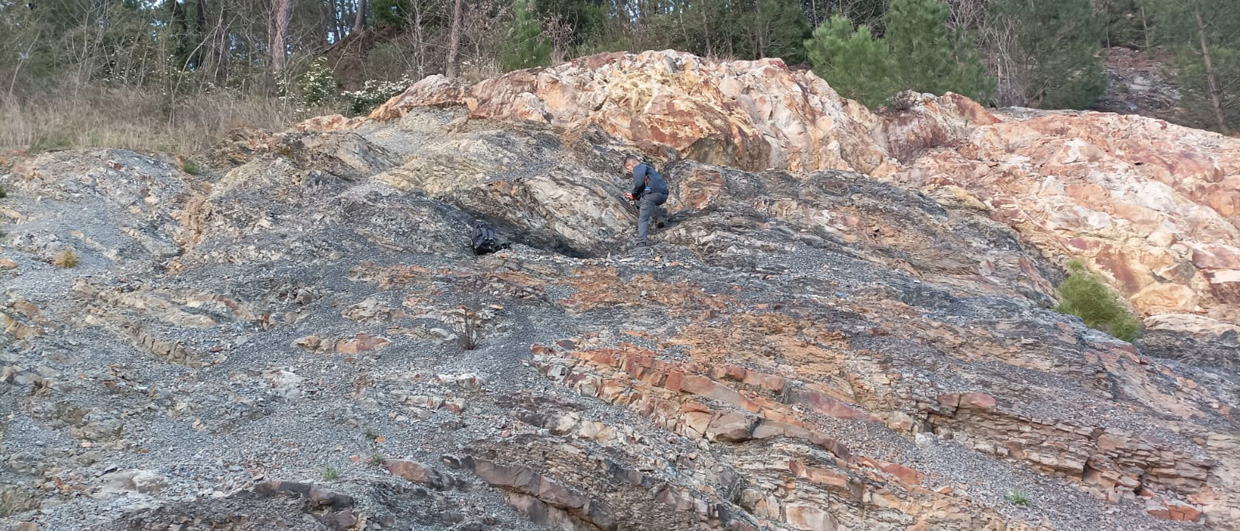
 The anisotropic velocity model is described by 5 parameters and is termed Tilted Transverse Isotropic (TTI). The elliptic shape displayed on the exposed rock face illustrates the variation of wave propagation speed which is higher along the geological bedding than perpendicular to it. When the Thomsen parameter ?? equals ?, this velocity surface becomes an ellipsoid, and the TTI is called elliptic. Image: CGGVeritasThe PSDM velocity model resembles the real, physical, earth model and its elastic parameters and describes the local propagation speed of seismic (sound) waves which vary throughout the model. This makes it easier to relate the PSDM model to other physical measurements of the earth, such as well information, gravity measurements, CSEM, or specific geological knowledge of the typical velocities expected in each layer in the model.
Anisotropic depth models described by five parameters are now the state of the art and are often termed Tilted Transverse Isotropic (TTI). Only a few years ago all PSDM models were isotropic with only the velocity to update, so the transition to the 5-parameter TTI representation has happened rapidly. The next step will be to allow velocity variation normal to the symmetry axis, which will further increase the accuracy of the images but will increase the number of model parameters and the complexity of the model even more. Our bat friend has a much easier task with only a single, constant isotropic velocity field to deal with.
Model building is the most complicated and time-consuming task in most PSDM projects. It is based on an iterative, top-down, process with repeated migrations creating many generations of increasingly improved models. Reflection tomography, scanning techniques and well log data analysis are key ingredients.
Depth Imaging vs Time Imaging
 Combining the wave fields from source(s) and receiver(s) through the imaging condition yields the seismic image. Image: CGGVeritasKirchhoff time migration has traditionally been the dominant imaging algorithm. Over the last few years depth imaging has become more popular and has started to replace time imaging. Computing capacity used to be a key limitation in the use of depth imaging, but with today’s modern computer clusters this is no longer a major issue. In parallel to the increase in computing capacity, a large range of depth imaging methods have been developed and are now used in the seismic industry.
Another reason for the continued widespread use of time imaging is that interpreters have traditionally been used to looking at images in the time domain and often prefer to continue to do so. However, it is easy to stretch the depth image to time by the velocity model used in the migration. There is also a general conception that depth migrated images do not preserve amplitudes as well as time migrated ones and therefore are not suitable for AVO or 4D applications. With the variety of PSDM methods currently available, this is the case for some methods, but not for others.
One key difference between time imaging and depth imaging is the way the velocity model is defined. In time imaging, the model is defined by the RMS velocity (i.e. time-averaged velocity) and optionally with the h-value giving the degree of anisotropy. These quantities are purely focusing parameters, in that they affect the residual move-out, but not the location of the structure. A change of RMS velocity at a particular location in the model changes only the focusing at that location.
See the invisible!
The key similarity between echo-location undertaken by bats and the depth imaging of seismic data is that they both form a detailed, spatial image, using characteristics of the propagation of pressure waves combined with a comparison (e.g. a cross-correlation) of the emitted and recorded fields. But whereas the bat forms the image in real time, the seismic depth imaging group spends weeks and months forming the final image using clusters of powerful computers. Where the bat uses zero-offset recordings with the source and the receivers in practically the same position, the seismic imaging group uses huge quantities of recorded data from a wide range of offsets, often exceeding 5,000 or 6,000m.
The rapid development of depth imaging and velocity model building methods means that we are now able to see into previously invisible parts of the subsurface in our search for the resources of the earth.


