Illuminating Resolution
The latest developments in high-tech seismic vessels and ‘mega’ channel counts both on and offshore have driven a revolution in seismic data acquisition.
From the Archive
 ‘Cover Story’. To subscribe to the magazine please use the menu at the top of the page.This ‘cover story’ from Geo ExPro Vol. 8, No. 3 is a fantastic introduction to the history of seismic acquisition technologies and how their evolution has increased the ‘illumination and resolution’ of the subsurface in an exponential way.
With over 10 years of publishing we now have an extensive archive of articles and feature pieces, many of which, as is the case with this article, are as current today as when they were written. Take some time to search our online database by using the search facilities at the top of this page. We hope you enjoy this article as much as we do.
The concept of using sound waves for exploring the subsurface is almost 100 years old. Inspired by the sinking of the Titanic in 1912, Canadian inventor Reginald Fessenden came up with the idea of using sound waves to detect the sea bed and icebergs. J. Clarence Karcher in the United States developed the principles into a reflection seismograph in the 1920s. In Europe, Ludwig Mintrop worked on refraction seismic, which he then took to the U.S. These early pioneers, and those that followed them for nearly 50 years, were restricted to two-dimensional or 2D seismic, recording profiles or cross-sections through the Earth.
3D Seismic Improves Accuracy
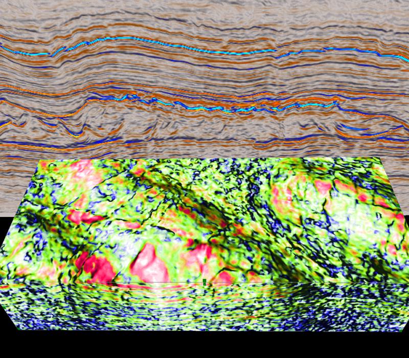 Improved resolution will be vital in future to extract the maximum information from the sub-surface, as shown in this sub-salt image from the UK North Sea. (Previously published in First Break Vol. 28, No. 10).In the 1960s it was realised that 2D seismic did not provide sufficient detail or accuracy, especially when seismic was to be used for guiding the development of oil and gas fields. So three-dimensional (3D) seismic was born, with the first survey recorded by Esso (now ExxonMobil) in the U.S. 3D not only provided an image of a volume of the subsurface rather than just cross-sections, it also allowed seismic processors to place sub-surface features such as dipping geological layers, faults and structures in the right location. Geoscientists soon found that maps of their oil and gas fields based on 2D were not correct. By the 1990s, 3D was seen by most operators as an essential tool not only in field development, but for exploration as well.
3D seismic requires data to be recorded over an area of the Earth’s surface, in order to image a volume of the sub-surface. This is relatively easy on land, where shot lines can be laid out at right angles to receiver lines, or Vibroseis sources moved along between lines of cables and receivers covering several square kilometres. But offshore, early 3D surveys had to be acquired with seismic vessels that towed only a single airgun array source and cable of hydrophone detectors (streamer). The first marine 3D surveys were essentially very closely spaced 2D lines, but this was inefficient and inaccurate. Gradually, marine systems evolved, first with seismic vessels that could tow more than one streamer and source array, and then with spreads that used multiple vessels. Sophisticated positioning combined the emerging GPS technologies with acoustic networks linking the cables.
Seismic technology developments were also driven by new thinking and research into acoustic wave sampling. Leo Ongkiehong of Shell and Ian Jack of BP, among others, promoted the idea that the seismic signal should be measured with receivers as closely spaced as possible along the cable, in order to recover the highest bandwidth (range of frequencies) reflected from targets in the sub-surface. Gijs Vermeer (then of Shell) introduced ‘cross-spreads’, a method of sampling the seismic wavefield fully by recording data from all shot-receiver distances (offsets) and directions (azimuths) within a survey. The twin goals of the seismologist became illumination and resolution – sampling the acoustic reflections from subsurface targets as completely and finely as possible.
3D Geometry Evolution
 Increasing the number of octaves in a seismic wavelet provides better resolution and more precise interpretation. (Source: CGGVeritas)When marine acquisition moved from 2D to 3D, the main drivers were economic – how to acquire as much data as fast as possible. Vessels started to deploy two streamers and then two airgun arrays in order to record four lines simultaneously. In the 1980s, seismic company GECO used two vessels in the ‘quad-quad’ system, acquiring 16 lines at a time. The feathering (displacement of streamers by currents) also required traces to be ‘binned’ – plotted at their correct shot-receiver location using the navigation data – so marine seismic was being recorded as a 3D volume rather than many 2D lines.
This technique allowed large 3D surveys to be acquired much faster than previously possible. But because each airgun array only fired once every four shots, the data were not being fully sampled. Noise caused by spatial aliasing – not recording sufficiently often along each individual cross-section in the 3D volume – was contaminating the data. Subsequent marine acquisition developments aimed to return to the ideals of Jack and Ongkiehong, improving sampling while maximising coverage.
Q-marine Integrated System
Towards the end of the 1990s, WesternGeco, now a Schlumberger company after the merger of GECO, Western Geophysical and other seismic providers, decided that the answer was to combine a number of acquisition technologies into a fully integrated and revolutionary system that would maximise resolution and minimise noise. This concept became the Q-Marine system that was deployed at the start of the new century. It is based on four main components – calibrated source, positioning, single sensors and steerable streamers.
In order to relate the seismic response to geology and hydrocarbon reservoir characteristics, the source signature – the shape of the outgoing signal – must be known accurately. Q-Marine has a source controller and measurement system that ensures every recorded shot can be calibrated with a notional signature. The calibration philosophy is continued into the positioning system, with acoustic networks down the streamers giving an accurate measurement of the location of each receiver for each shot. Within the streamers, the sensors, closely spaced hydrophones, are recorded individually and the effect of perturbations removed automatically. The streamers are steerable using devices called Q-Fin and are filled with a solid gel neutrally buoyant material, rather than liquids such as kerosene used in the past. These measures increase resolution and reduce noise in the recordings. Steerable streamers also allow the desired coverage to be obtained more accurately, important for time-lapse of 4D surveys that repeat the geometries of previous acquisition. The Q-Marine system is now available on most of the WesternGeco fleet. With 3.125m receiver spacing, a typical spread could have 30,000 channels.
Revolutionary Vessel Designs
Also in the 1990s, another merge of seismic companies created Petroleum Geo-Services or PGS. From the start, the main focus of PGS was high resolution 3D. It considered that the key to obtaining the best resolution combined with efficiency was a high channel count with as many streamers as possible. PGS grabbed the headlines with their novel Ramform designs, delta-shaped seismic vessels based on ‘stealth’ designs that generated little noise but had wide ‘back decks’ that could deploy many streamers. These were introduced in the mid 1990s and in the intervening years have gone through several generations, with ever wider back decks, streamer numbers and streamer lengths. PGS is now building its latest offering, the Ramform W-class, which will have a staggering 26 x 12,000m streamer capacity. PGS, like many seismic companies, has also embraced the solid streamer. Their entire marine fleet is now equipped with these gel-filled streamers.
PGS new Ramform ‘W-class’ seismic vessel. (Source: PGS)
CGGVeritas has also aspired to higher marine channel counts and noise reduction. It has introduced the Sercel Sentinel® solid streamers. Sentinel streamers are filled with a polymer foam rather than the gel of other solid streamers. CGGVeritas believes these foam streamers are the quietest available. Streamer positioning is achieved and measured with Sercel’s integrated steering, depth control and acoustic Nautilus™ system.
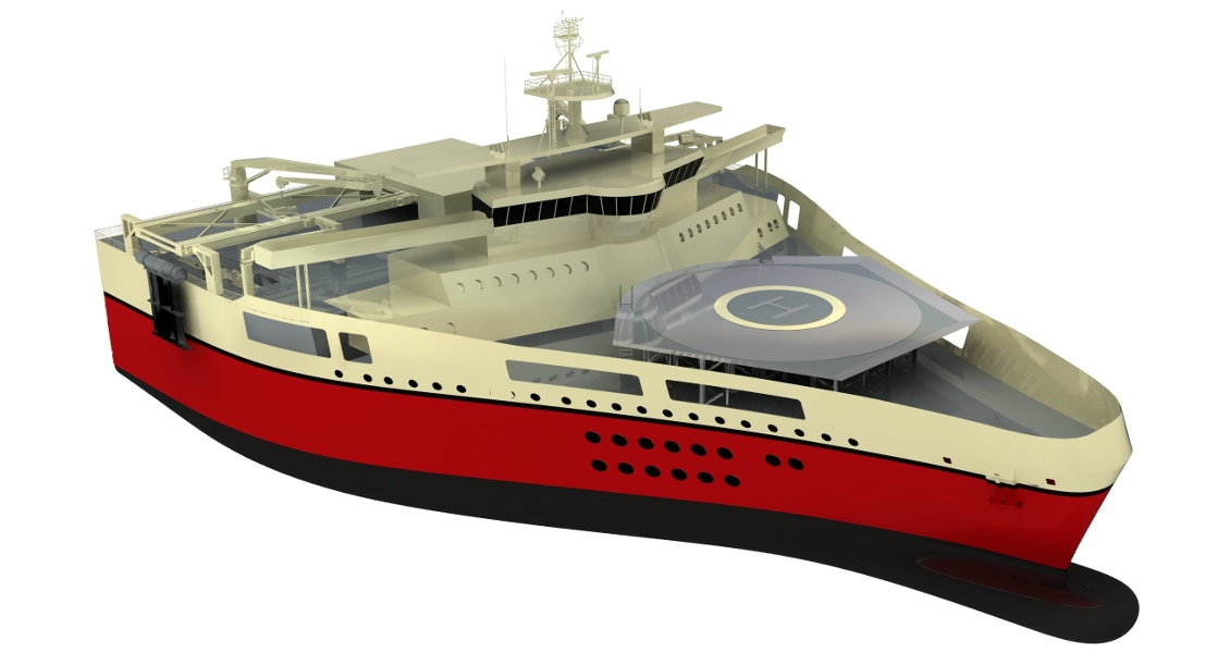
CGGVeritas, like other seismic companies such as Polarcus and WesternGeco, has also introduced the distinctive low-emission ULSTEIN X-BOW design of seismic vessels to further reduce acquisition noise. Their vessel ‘Oceanic Vega’ can deploy up to 20 streamers, with the maximum so far deployed being twelve streamers of 8,100m length.
Improving Land Resolution
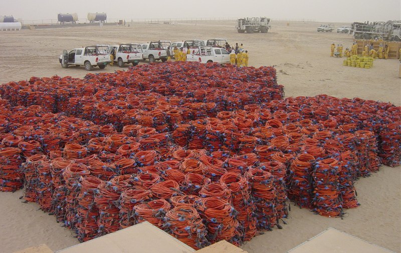 Equipment for a CGGVeritas ‘super-crew’ ready to go! (Source: CGGVeritas)CGGVeritas is also well known as a land acquisition specialist and with its ‘super-crews’ has come close to realising the Vermeer ideal of cross-spreads. Modern land acquisition systems like Sercel’s 428XL have been field proven at more than 80K channels and can use new technology detectors like MEMS (Micro-Electro-Mechanical Systems) accelerometers. Wireless systems aim to take mega-channel systems into rugged and remote territory. In a recent survey in the Middle East, CGGVeritas recorded 25,000 live channels per Vibroseis ‘shot’, each into a 36 line spread of 5km x 4.2km. Source and receiver sampling was 7.5m, yielding exceptionally high fold and resolution. Super- crews also use techniques to improve production, such as recording more than one Vibroseis source simultaneously and have matched or even exceeded marine production rates. After a survey conducted by a CGGVeritas joint venture in Oman, Petroleum Development Oman’s Chief Geophysicist Bob Sambell said “A reasonable estimate (is) the expected additional discoveries would pay the cost of the survey a hundred times over”.
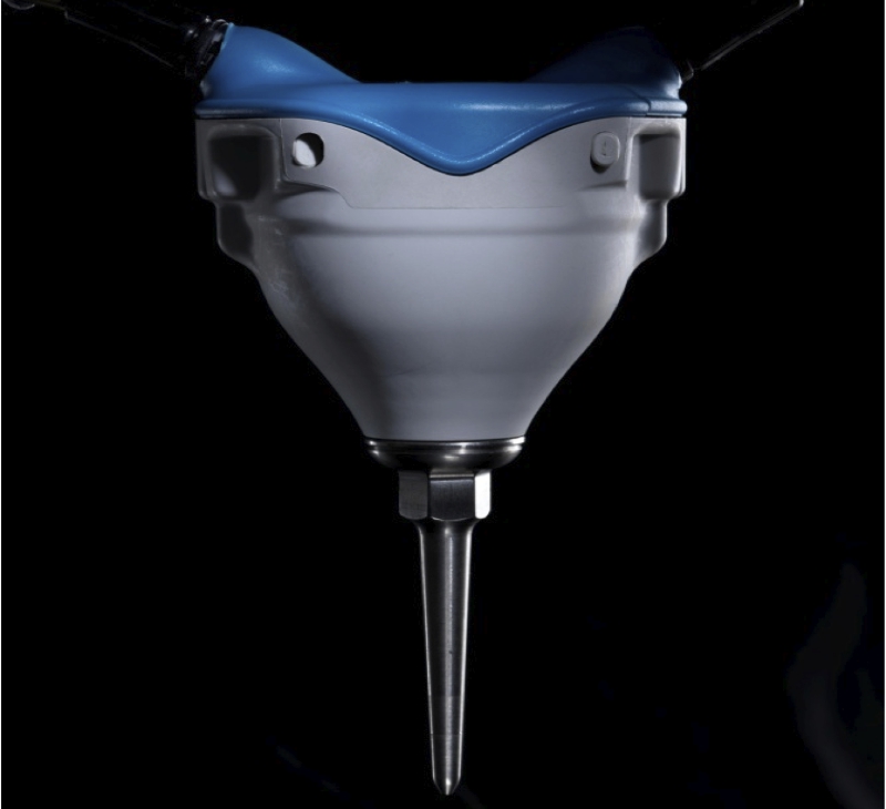 GAC sensor unit from UniQ land acquisition system. (Source: WesternGeco)WesternGeco has also developed the UniQ system, taking the Q-Marine concept onshore. As with Q-Marine, UniQ integrates a number of proprietary technologies into a seamless system. The point receiver system has a notional channel count of 150,000, though it is scalable beyond this if required. At each receiver, a GAC (Geophone Accelerometer) unit contains the sensor, with end-to-end cables connecting to power and digitising boxes. This eliminates geophone cables, saves weight and increases the efficiency of land crews.
The GAC accelerometers reduce distortion and extend bandwidth, especially at low frequencies, compared to geophones. The hardware is combined with processes like DGF (Digital Group Forming), a software solution to tailor noise rejection to local conditions. As array-forming is a processing step, UniQ allows for a range of geometries including random detector placement.
Capturing All Azimuths
Whereas on land all azimuths can be captured by laying out an appropriate spread, this is more difficult for marine. This was recognised in the early days of marine 3D when discussions sprang up as to whether one should shoot ‘dip’ (as far as possible in the direction of the main geological dip), or ‘strike’. In the Gulf of Mexico, completely different images were obtained by shooting across a salt dome, where seismic energy could be distorted, or just along its edge, where it might be possible to ‘undershoot’ overhanging salt, revealing hydrocarbon traps. This highlighted the need to record both dip and strike; in fact, as many azimuths as possible. The problem was that 3D with only a few cables still had limited azimuths except on very short offsets. Widening the spread with more streamers improved the situation and in the 1990s, when exploration was moving beneath the salt, several different techniques developed. These included shooting several lines in different directions (Multiple Azimuth, or MAZ), or with multiple vessels, perhaps with extra shots from across and behind the spread (Wide Azimuth or WAZ).
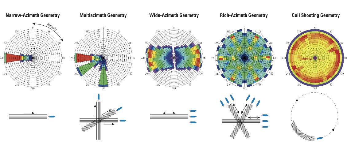
Various marine acquisition geometries – colours show number of traces (fold) in each offset and azimuth range with dark blue the lowest and red the highest fold. (Source: WesternGeco)
None of these methods sampled all azimuths for all offset ranges, though. Offshore, this could only be obtained by very closely spaced ocean bottom sensors, today still prohibitively expensive for high-resolution 3D. One answer came from reviving an idea of Bill French’s from the 1980s, to sail in circles round salt domes. At the time, the hardware was not really up to the job, but this Full Azimuth (FAZ) technique has now been taken up by WesternGeco as ‘Coil Shooting’. A 3D survey is covered by a series of overlapping near-circles until the desired sampling is obtained. These methods have been described in more detail in the series of GEO Expro articles by Landrø and Amundsen from April 2008 onwards. WesternGeco has now expanded the idea in ‘Dual Coil Shooting’ to capture very long offsets of 12-15km. This returns to the multi-vessel concept, using two vessels at opposite sides of the coil and two extra source vessels.
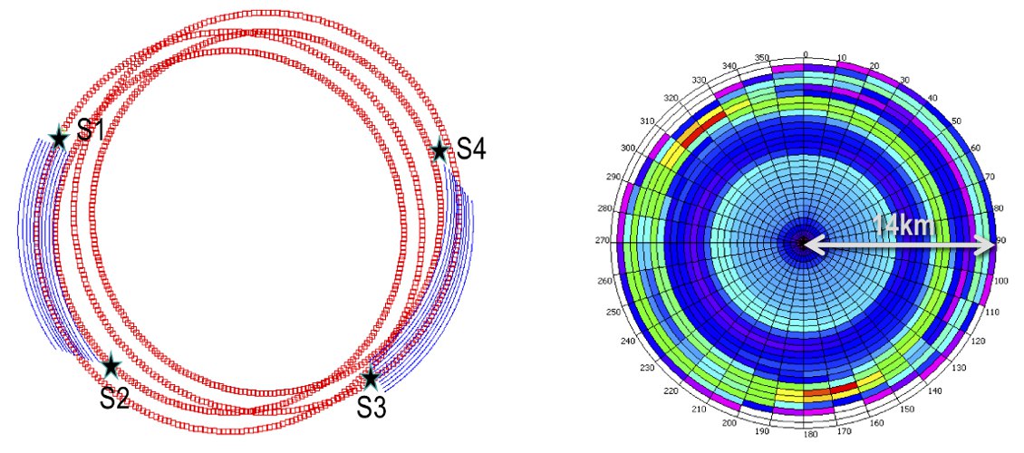
Dual coil configuration: two receiver vessels and two source vessels. (Source: WesternGeco)
A different approach to improve coverage is being tried by PGS who recognise that, with very wide towed spreads, the source sampling in the crossline direction is sparse. Short offsets in particular and therefore shallow data are not fully recorded. PGS has developed a technique called HD3D that improves this sampling by interleaving adjacent sail lines. This method improves coverage and means that they can remove surface multiples, the seismic energy reflected from the sea-air interface, more effectively.
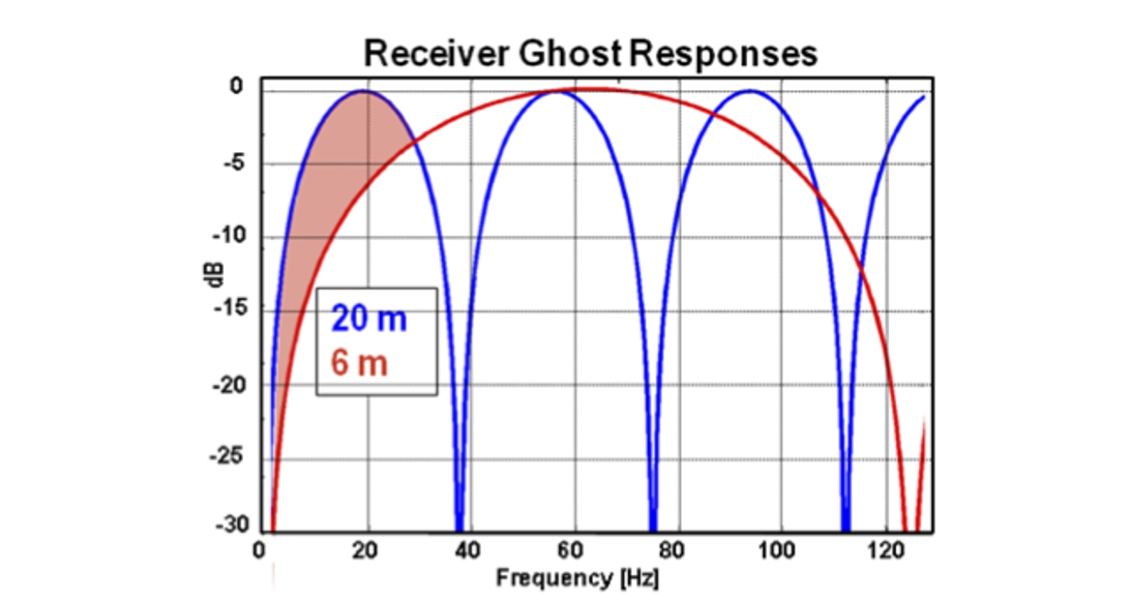
Ghosts Limit Bandwidth
In spite of all the attempts to record fully and finely sampled data, multiple signals called ghosts are a fundamental limitation in extending the seismic bandwidth towards both high and low frequencies. Maximising bandwidth is important for higher resolution and for techniques such as seismic inversion – determining geological properties directly from seismic – and stratigraphic prediction. The hydrophones, pressure sensors in the streamers, record the seismic signal reflected from the subsurface, but also, slightly later, the same signal that has bounced back from the sea surface – the ghost. The ghost is reversed in polarity and cancels out at frequencies dependent on the streamer depth – creating ‘notches’ in the recorded seismic spectrum. Towing the streamer shallower can achieve higher frequencies but limit the lower ones and vice-versa. The goal, to extend the spectrum in both directions, is now being approached by different seismic companies in different ways with a set of new technologies. WesternGeco have introduced DISCover (Deep Interpolated Streamer Coverage). The Q-Marine system allows not only many cables to be towed, but permits the precise positioning of those cables both laterally and in depth. The DISCover system uses cables towed both shallow, to capture high frequency data, and deep, for the low frequencies. It may seem at first that this could be a costly and operationally difficult solution, but the trick lies in only using sparse sampling on the deep cables, with perhaps only one deep cable for every four shallow ones. This works because the deep cables are only sampling low frequencies which can be interpolated between the cables without losing resolution. An analogy is in modern surround-sound hi-fi systems that have several small speakers for directional sound, but only use a single bass ‘sub-woofer’ for the low frequencies.
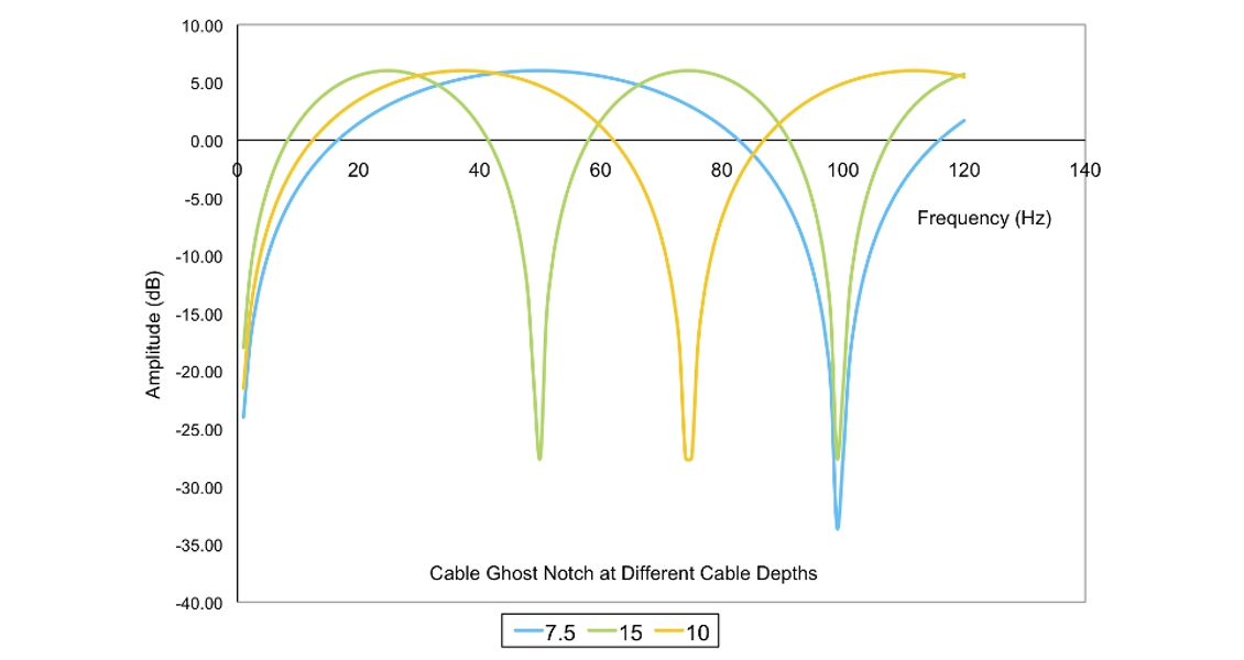
Notches in the amplitude spectrum caused by ghosts at different streamer depth lead to compromises in data quality during survey design. (Source: CGGVeritas)
Improvement in low frequency response in WesternGeco’s DISCover system when adding deep cable signal (blue) to shallow (red). (Source: WesternGeco)
CGGVeritas approaches the problem in a similar way, but using variable depth streamers in a system called Broadseis™. As with the other seismic companies, solid streamers and streamer control have now improved to the stage where their positioning is much more accurate. At the longest offsets in a cable, high frequencies are most attenuated, so Broadseis increases streamer depth with offset, recovering high frequencies near the vessel but aiming to maximise low frequencies further away. With a curved streamer shape, the system records a broader band of signal than previously possible, with frequencies down to 2.5Hz. The exact geometries can be optimised for each survey and, together with the special processing needed for this system, are proprietary to CGGVeritas.
Improvements in WesternGeco DISCover technology when adding data from deep streamers. (Source: WesternGeco)
Improvements in WesternGeco DISCover technology when adding data from deep streamers. (Source: WesternGeco)
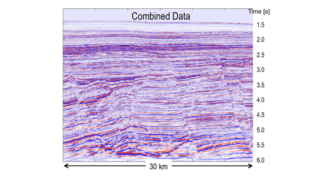
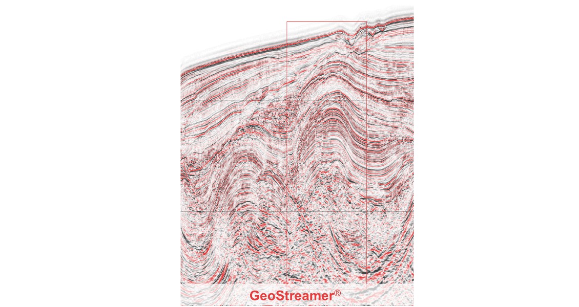
The PGS solution to the bandwidth problem is called GeoStreamer®. This uses a different technology from the other two companies, relying on two component receivers hitherto limited to land or sea bed seismic systems. If two different sensors are used at the same location, they act in different ways. Pressure sensors (hydrophones) and velocity sensors (similar to land geophones) both record the seismic signal (upgoing wave) as positive polarity, but the ghost (downgoing wave) as negative for the hydrophone and positive for the velocity phone. Summing the recordings of the two sensors removes the downgoing wave (de-ghosting), leaving only the signal. Because the ghost is removed, the high frequencies remain and the streamers can be towed deeper, enhancing low frequencies as well. With a deeper tow, the acquisition system is also not as susceptible to noise generated in bad weather.
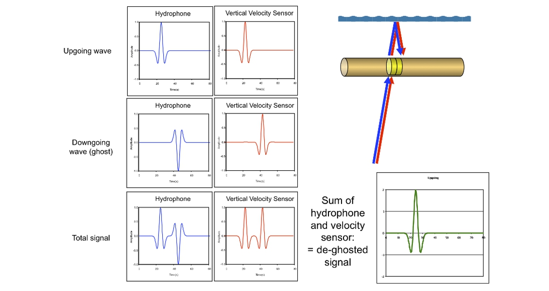
Separating up- (signal) and down-going (ghost) energy with dual sensors – signals sum but ghosts cancel out. (Source: PGS)
PGS has now equipped about half of its marine fleet with GeoStreamers and has observed a 4 to 5 fold boost in low frequencies and an overall improvement in the frequency range of some 60%. This has improved results from advanced signal processing such as seismic inversion. An additional benefit of the dual sensors is that the information needed for PGS’s surface multiple removal processing, SRME, is measured directly.
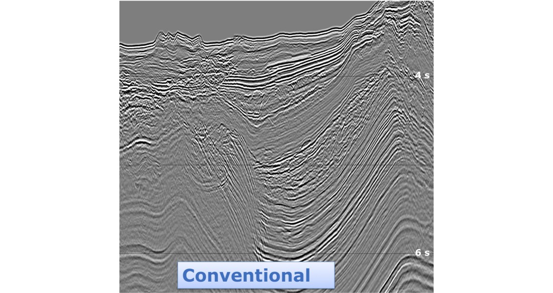
CGG Veritas legacy data set from NW Australia and equivalent Broadseis™ (Source: CGGVeritas Data Library)
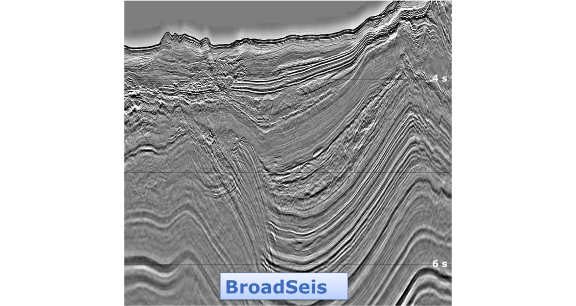
CGG Veritas legacy data set from NW Australia and equivalent Broadseis™ (Source: CGGVeritas Data Library)
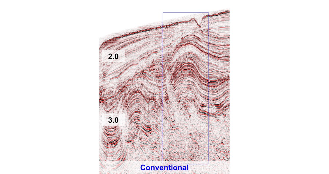
PGS conventional and GeoStreamer® acquisition offshore West Africa. (Source: PGS)
PGS conventional and GeoStreamer® acquisition offshore West Africa. (Source: PGS)
Future developments?
The past two decades have seen significant advances in the technologies needed to meet the twin goals of a fully illuminated and high resolution image of the subsurface. What will the next twenty years bring? For the offshore, Landrø and Amundsen had a go at crystal ball gazing in the fourth part of their GEO ExPro articles in 2008, citing ocean bottom surveys that use autonomous underwater vehicles, or a ‘net’ of detectors towed behind a vessel. On land, CGGVeritas expect that systems deploying 200,000 single sensor channels will soon be deployed. True wide-azimuth acquisition and processing should help unlock unconventional hydrocarbons by focussing on ‘sweet spots’.
In a 1992 article in SEG’s ‘The Leading Edge’, Woody Nestvold, Shell Chief Geophysicist asked “3D seismic – is the promise fulfilled?” His answer was a resounding ‘Yes’! But how much more has it been fulfilled today! The resolution revolution is still in progress – we can only imagine what it may bring in the future.