Gas Hydrates – Part V: The Resource Potential
The gas hydrate resource is a function of geology, technology, policy, and market conditions. As we have seen, the commercial resource and recovery potential of gas hydrate strongly depends on the type of gas hydrate accumulation. In Part V of our series on gas hydrates, we discuss the resource potential.
Natural gas hydrate occurs worldwide: in oceanic sediments of continental slopes; in deepwater sediments of inland lakes and seas; and in both continental and continental shelf polar sediments. In oceanic sediments, where water depths exceed about 300m and bottom water temperatures approach 0°C, gas hydrate is found at the seafloor and down to sediment depths of about 1,100m. The typical depth range for hydrate stability lies 100–500m beneath the seafloor. In polar continental regions, gas hydrate can occur in sediments at depths ranging from 150 to 2,000m. Occurrences of hydrates within the gas hydrate stability zone (GHSZ) are affected by numerous additional factors, including availability of gas, water, and geological controls. About 98% of the gas hydrates are believed to be concentrated in oceanic sediments, while the other 2% are in polar landmasses.
How Much Gas Hydrate Exists?
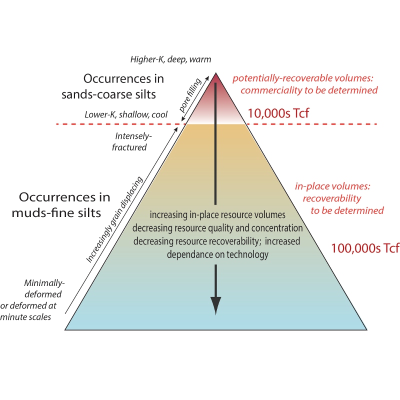 Gas hydrate resource pyramid: Gas hydrates exist in a variety of forms that pose different opportunities and challenges for energy resource exploration and production. The left axis displays lithology of the host sediment. The right axis shows associated estimates of natural gas resources. Gas hydrate-bearing sands are the most feasible initial targets for energy recovery. Other occurrences, such as gas hydrate-filled fractures in clay-dominated reservoirs, may become potential energy production targets in the long-term future (Courtesy: Ray Boswell).Gas volumes are often cited in units of trillion cubic feet (Tcf), and there are approximately 35.3 cubic feet in a cubic metre. It is estimated that resources of methane in natural hydrate reservoirs range anywhere from 105 to 2.8 x 10⁶ Tcf, or around 2.8 x 10¹⁵ to 8 x 10¹⁵ m3, indicating that more carbon is contained in methane hydrate than in all other organic carbon reservoirs on earth combined.
These estimates, however, include hydrate in low-grade shale deposits as well as in high-grade sand deposits. Only a fraction of the methane sequestered in global gas hydrate deposits is likely to be both concentrated and accessible enough to ever be considered a potential target for energy resource exploitation.
The relative amounts of gas hydrate in the global system can be illustrated by the hydrate resource pyramid, which captures the distribution of sequestered methane among the major types of global gas hydrate deposits. Only the hydrates at the top of the pyramid – a small subset of the hydrate deposits – are likely to be considered viable as a source of commercial quantities of natural gas.
Occurrences in Muds and Coarse Silt
At the top of the pyramid lie high permeability sediments in permafrost areas. The amount of gas hydrate in these settings globally is relatively small, but permafrost-associated gas hydrates might be the easiest to commercialise, particularly in areas with well-developed infrastructure from conventional hydrocarbon production, such as the Alaskan North Slope.
Gas hydrate resources housed in marine sand reservoirs are also obvious major targets for any longer-term development of gas hydrates as a resource. Highly permeable marine sands with moderate to high gas hydrate saturations are considered the best targets for resource development. Recent logging-while-drilling in the Gulf of Mexico has identified geologic units with inferred hydrate saturations as high as 80%.
Reservoir quality is expected to increase with increasing grain size. However, the primary control of importance may be intrinsic permeability. Sediments of high intrinsic permeability may have the capability to host hydrate at high saturations (50–90% of pore space).
Occurrences in Muds and Fine Silt
Below marine sands in the gas hydrate resource pyramid is the category for muds and fine silt. Fractured muds are less permeable, usually smaller-grained sediments that may host gas hydrates in fracture-related permeability. Drilling on the Indian and Korean margins and in the Gulf of Mexico has found gas hydrate filling pervasive fractures within low permeability sediments (e.g., silts and clays). Such sediments may not have a high average saturation of gas hydrate, maybe around 20%, but targeted production from gas hydrates within the fractures could theoretically yield significant gas.
At the base of the resource pyramid lie gas hydrates in low permeability, undeformed fine-grained muds. Such sediments host most of the global gas in place in methane hydrates and are unlikely to become a target for commercial production of gas from methane hydrates. The saturation typically is only 5%.
Sea-floor mound deposits are small size and ephemeral. They are environmentally sensitive due to associated unique biological communities and thus unattractive as a resource target.
Potential Worldwide
 Hydrate Energy International (HEI) recently released estimates of the gas hydrate resource potential, utilising a petroleum systems approach (Source: Johnson, 2011).In conventional petroleum systems analysis, the geological components and processes necessary to generate and store hydrocarbons are well established: source, migration, reservoir, seal, and timing. To apply this petroleum system model to a methane hydrate resource system, one needs also to incorporate the parameters that determine methane hydrate stability conditions: formation temperature and pressure, pore water salinity, water availability, gas source, gas transport, gas concentration, and the time over which the system evolves.
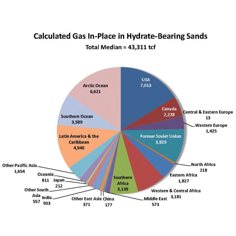
Recently, Hydrate Energy International (HEI), as part of the Global Energy Assessment being conducted by the International Institute for Applied Systems Analysis (IIASA), released the results of a new evaluation of the gas hydrate resource potential, utilising a petroleum systems approach. Their median assessment is around 43,000 Tcf.
Geological Settings of Gas Hydrate
Gas hydrates occur in a wide variety of geologic settings and modes of occurrence. These include gas hydrate concentration, host lithology, distribution within the sediment matrix, burial depth, water depth, and many others. The major controlling factor on where gas hydrate forms is lithology and availability of methane.
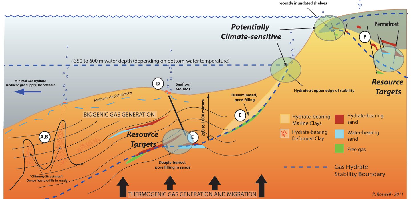
The HOTSPOT IMAGE (below) from Boswell (2011) gives a schematic depiction of the components of various methane hydrate systems. Examples A and B represent massive forms in hydrate-bearing marine clays. Example C shows a hydrate-bearing marine sand. Examples D and E represent sea-floor mounds (outcrops) and hydrate-bearing clays (finely dispersed).
Three dominant types of gas hydrate accumulations can be defined and distinguished based on the mode of fluid migration and gas hydrate concentration within the GHSZ (Milkov and Sassen, 2002). The end-members are structural and stratigraphic accumulations, but combination accumulations controlled both by structures and stratigraphy may occur.
+
–
 CA, BDEF
HOTSPOT IMAGE: A schematic depiction of the components of various methane hydrate systems.
Typical methane hydrate reservoir morphologies include (A) networks of hydrate-filled veins; (B) massive hydrate lenses; (C) grain-filling methane hydrate in marine sands; (D) massive sea-floor mounds; (E) grain-filling methane hydrate in marine clays; (F) grain-filling methane hydrate in onshore arctic sands/conglomerates (Click on map for photographic examples).
The general location of the most resource-relevant (blue circles) and most climate-relevant (green circles) methane hydrate occurrences are also shown. Other parts of the methane hydrate system as depicted include the relationship between microbial and thermogenic gas sources and gas migration controls.
SOURCE: R. Boswell, 2011.
Structural Accumulations
Structural gas hydrate accumulations occur in advective high fluid flux settings, where highly permeable fractured conduits like fault systems, mud volcanoes and other geological structures facilitate rapid fluid transport from depth into the GHSZ. The gas hydrate concentration in the sediments is relatively high. Gas hydrate deposits associated with active faults and craters of deepwater mud volcanoes usually present high gas hydrate concentrations, with 30–50% of the pore space filled by hydrates.
The shallow seafloor consists typically of non-consolidated silts and clays. Various types of gas hydrates may occur: layers of hydrates of thicknesses from millimetres to tens of centimetres, massive hydrate deposits, or hydrate outcrops (mounds) on the seafloor.
Bottom-simulating reflectors (BSRs) are not common in structural accumulations as they do not typically seal much gas below the gas hydrate layer. If present, they are patchy and displaced and they do not parallel the seafloor.
Stratigraphic Accumulations
Stratigraphic gas hydrate accumulations generally occur in advective low fluid flux settings within passive margins in relatively coarse-grained sediments, from biogenic methane gas generated in situ, or gas which is slowly supplied from deeper in the subsurface.
In stratigraphic accumulations, gas hydrate tends to be highly dispersed through the GHSZ, and low hydrate concentrations are commonly measured; 1–12% of the pore space is filled by hydrates. The low hydrate concentration can be explained by the low permeability and porosity in clay-rich sediments, which hinder the mobility of both water and gas, necessary for hydrate formation. Most of the hydrate in clay-dominated sediments is present in a network of tiny fractures.
However, there are significant exceptions. Both the lithostatic pressure (depth) and the sediment type influence how the gas hydrate will occupy the sediment pore space. Deeper in the sediment column below the seafloor, the hydrate cannot overcome the lithostatic pressure between the sediment grains and must reside in the pore space or in fractures. For coarse-grained sediments, such as sands, hydrates can become highly saturated.
A well-known example is the Nankai Trough, where gas hydrate occupies up to 82% of pores in thin but very permeable sand units. The Nankai Trough is located beneath the Pacific Ocean off the south-east coast of Japan, and is known as an active subduction and earthquake zone. BSRs are commonly observed on the eastern Nankai margin. This is to date the only place where a successful gas hydrate production test has been performed.
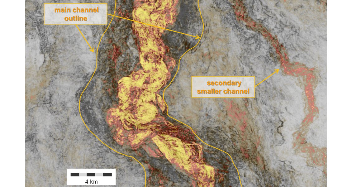
Seismic attribute co-blend map (RMS amplitude/coherence) showing sand channels in excess of 150m thick. The bright yellow and orange colours highlight zones with high seismic amplitudes characteristic of sand channels. The displayed interval shows several generations of sand deposits within the gas hydrate stability zone. If charged with gas they could form prospective targets for gas hydrate exploration. (Reichel and Gallagher, 2014)
Mapping of Gas Hydrate
Interpretation of seismic data provides the most important means for mapping and characterising the distribution of gas hydrates and possible underlying free gas. Shallow high-amplitude events can be generated by features other than gas hydrate – for example, carbonate cemented zones, layered clays, the bases of mass transport complexes, and unconformities. However, the presence of seismic bottom-simulating reflectors is the most common indicator of the presence of gas hydrate. The BSR is often a strong, coherent reflector that lies at the base of the gas hydrate stability zone and is overlain by sediments containing gas hydrate and underlain by sediments containing free gas. The BSR has negative reflection amplitude caused by the difference in elastic impedance. The base of the free-gas zone is rarely evident in the seismic section and the concentration of free gas is thought to decrease gradually downward to water-saturated sediments. In rare cases we may observe a flat spot – in exceptional cases, as in the illustration below, even two – beneath the BSR.
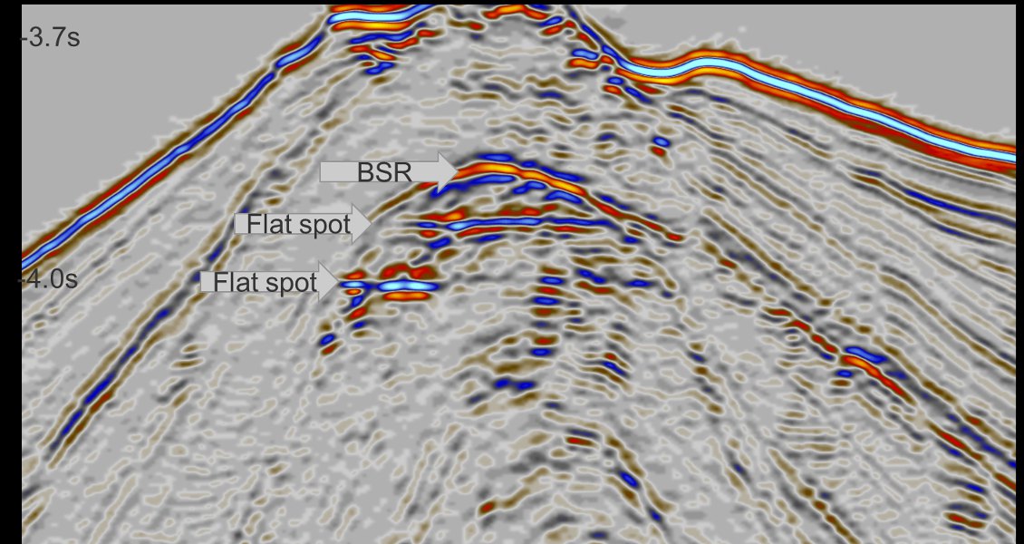
Seismic example of marine gas hydrates above a double flat spot. The contrast between the high-velocity hydrate-bearing strata and the low-velocity gasbearing strata beneath results in the bottomsimulating reflector (BSR). In this example, the gas hydrates act as seals for underlying hydrocarbon reservoirs (Courtesy: Statoil, Sonangol E.P. and Schlumberger Multiclient)
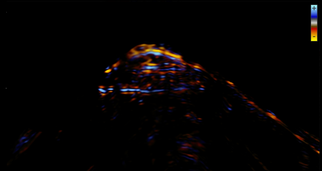
Seismic feature enhancement of BSR and two underlying flat spots (Courtesy: Statoil, Sonangol E.P. and Schlumberger Multiclient).