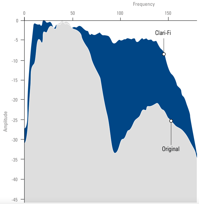
The oil industry is increasingly recognising the benefits of broadband data. Broadband seismic provides a greater richness of both robust low frequencies – ideal for deep structure imaging and inversion stability – and high frequencies – which aid temporal resolution. TGS’s Clari-FiTM is a proprietary three-step processing solution which allows broadband pre-stack seismic data to be generated from conventionally acquired seismic data, e.g. using single sensor streamers towed at a constant depth. Marine seismic data acquired with an airgun source and recorded using pressure sensors towed at a constant depth has been the standard for offshore oil and gas exploration for thirty years. An inherent limitation with this technology is that its useable bandwidth is restricted, typically to around 70 Hz (bandwidth is defined as the difference between the upper and lower useable frequencies). Delivering increased bandwidth (i.e. broadband) data for exploration and production purposes has numerous advantages. However, two major factors serve to significantly reduce the useful bandwidth of the source wavelet. The first is the interference between the source pulse and reflections from the water surface – ‘ghosts’ – and the second is the fact that the earth acts as a filter which attenuates high frequencies in the source wavefield as it travels through the earth. In order to obtain truly ‘broadband’ seismic images, both factors need to be addressed. TGS’s Clari-Fi is a proprietary 3-step processing solution which accounts for both ghosts and the earth filter, allowing broadband pre-stack seismic data to be generated from conventionally acquired seismic data. Early in the processing sequence, the effects of the source and receiver ghosts are suppressed using a multi- dimensional deconvolution. This pro cess repli cates the benefits of broadband acquisition. Furthermore, after conver sion to zero-phase, boosting operators can be applied to minimise the decay constraint between 3 to 7 Hz – a result of the inherent limitations of the signal output from marine airgun arrays – there by maximising the signal in this band. The decision to apply these steps at the beginning of the data processing sequence is considered key for two reasons. Firstly, the applied operators do not discriminate between signal and noise, but choosing to apply the operators at the beginning of processing enables all of the signal enhancing com-ponents in the processing sequence to work on the broadened spectrum. Secondly, seismic horizons related to deep structural geology are more easily identified in low frequency enhanced data. In con sequence, more accurate velo city models can be produced throughout the processing sequence. The result of the earth’s attenuation is a preferential loss of higher frequencies during wave propagation, which induces a ‘tilt’ in the spectral content of deeper horizons. This attenuation is commonly expressed as effective Q, Qeff, which is a combination of the intrinsic attenuation Qint, describing energy loss due to the propagation media, and apparent attenuation Qapp, describing attenuation due to scattering, transmission, mode conversion, etc. An important feature of broadening the spectrum in Step 1 is that more accurate measurements of the effective Q, Qeff, can be calculated from the data itself. Therefore, the attenuation caused by the earth’s filter can be determined and solved for on the pre-stack data. This is beneficial for deeper targets as the apparent tilt in the spectrum is minimised. An important aspect of the Clari-Fi process is careful de-noising of the data. Any process that seeks to broaden the spectrum must take care to broaden the signal spectrum and not the noise. In order to maximise the whitening of the signal spectrum, a multi-dimensional noise attenuation approach is used. Several noise attenuating processes are performed in all of the available ‘time-offset’ domains. Noise attenuation techniques are applied in the shot, receiver, common mid-point (CMP), and common offset domains to enhance low frequency sub-basalt primary signal, and minimise both coherent and incoherent noise. Techniques employed include coherent noise attenuation using a time and space variant f-x apparent velocity dip filter; several iterations of an algorithm which decomposes data into frequency bands and identifies and attenuates anomalous amplitudes within those bands based on time variant thresholds; and multiple passes of time and space variant f-x deconvolution – regularly operating only below the top or base of highly attenuative horizons. The 100 km seismic line displayed on pages 75–76 was acquired in 2006 using an 8 km conventional streamer towed at a depth of 9m. The data were reprocessed in 2012 using Clari-Fi. It represents a strike line through the Flett Sub-basin in the Faroe Shetland Basin and ties the Laggan field with gas reservoired in the Vaila sandstone. The enhanced resolution now available enables a much greater degree of confidence to be placed on the seismic correlation of events across faults, with the improved low frequency component of the data providing the greatest benefit. The data appears ‘shaded’ or ‘textured’ with the shading representing geological units rather than a top and base unit. The increase in resolution can be clearly seen in the examples shown here. In order to achieve true broadband images, attenuation caused by both ghosts and the earth’s filter must be addressed. TGS’s proprietary Clari-Fi imaging technique represents a robust methodology which deals first with the ghost effect, and then solves for the earth’s attenuation. The method yields seismic images that are broadband and focused, thus improving the resolution of the data. This technique works with con ventional streamer acquisition and so enables reprocessing of legacy data. Furthermore, since Clari-Fi is an amplitude preserving pre-stack process, gathers are automatically available to drive AVO and inversion studies. For more information, contact TGS at: imaging-info@tgs.com
Clari-Fi™ Broadband Data from Conventional Streamer Acquisition
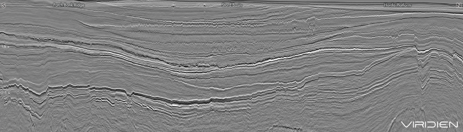
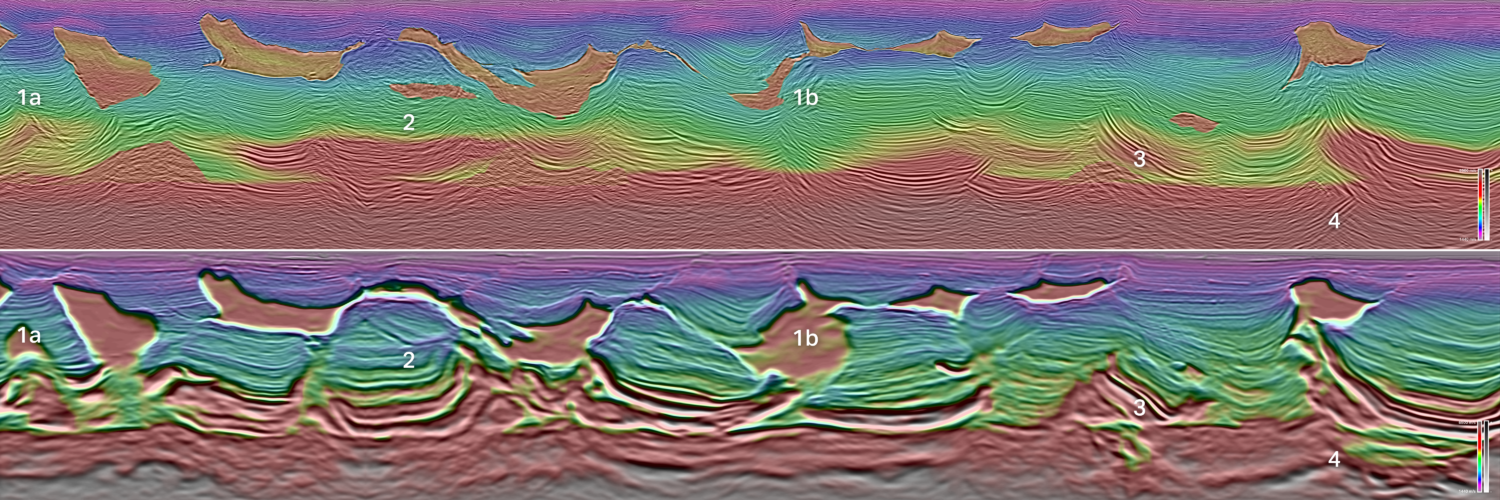
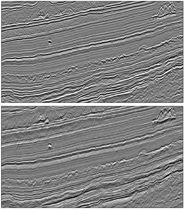
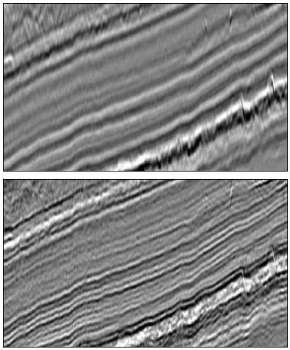
 100 km seismic line from the Faroe Shetland Basin, acquired in 2006 with conventional acquisition parameters and reprocessed in 2012 using Clari-Fi.
Clari-Fi your data
The quest for broadband marine seismic
Step 1: spectral processing
Step 2: effectively solve for the Earth’s attenuation
Step 3: Multi-domain Noise Attenuation
Summary
Related Articles