Monitoring of the Ekofisk Field
Installing a Life of Field Seismic system on Ekofisk will help understand reservoir depletion and ensure future production wells are drilled where there is still oil left.
ConocoPhillips, operator of the Norwegian PL018 license, will install a recording system for permanent seismic monitoring at the Ekofisk Field in 2010. The scheme will allow for cost-efficient, high-quality and highly repeatable 3D 4C (4-component) seismic acquisition twice a year.
The main objective of the system is to undertake comparative “time-lapse”, or 4D seismic, analysis for improved understanding of reservoir depletion zones and injected water expansion fronts within the reservoir interval, thereby reducing the drilling and production risks for future production wells.
A second objective is to improve structural imaging of the “gas-obscured” crestal area which covers approximately one-third of the field.
Unlike receivers in a seismic streamer, which only record compressional waves, 4C receivers located on the seafloor also record shear waves reflected from the subsurface. Reflected shear waves are important for imaging through the “gas-obscured” area at the crest of Ekofisk. By combining compression and shear waves it is possible to derive more accurate elastic properties of the overburden and the reservoir.
A third objective is the utilization of 3D 4C seismic data to reduce drilling risk in the overburden.
4D Seismic Observations
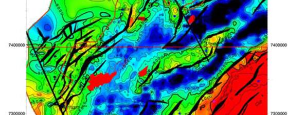
 4D travel-time changes at Top Ekofisk from 1999-2003, 2003-2006 and 2006-2008. The images show a propagating waterfront from injector well K3 towards producers X16, X28 and M17 which were put on production in the period 2003-2005. Positive time shifts are a result of reservoir compaction and decreased seismic velocity in the sediments above top reservoir. © ConocoPhillipsChanges in seismic signals over time (4D), as observed by repeat 3D surveys over producing fields, are a result of alterations in reservoir fluid composition and pore pressure caused by production and injection programs. Normally, the dominant 4D effects are time and amplitude changes in the reservoir, as porosity remains unchanged. However, in highly porous chalk fields such as Ekofisk, 4D changes are also transmitted into the overburden due to reservoir compaction during depletion and water injection.
The compaction-induced geomechanical changes in the overburden results in large 4D effects, measured as changes in two-way travel-time between surface and top reservoir. Joint interpretation of the five Ekofisk 3D seismic streamer surveys (1989, 1999, 2003, 2006 and 2008) has revealed overburden travel-time differences as large as 20 ms.
Production and injection data from wells prove the overburden travel-time differences to be strongly correlated to the underlying reservoir compaction. In fact, detectable travel-time differences are observed at wells which have been active for less than a year.
A second and subtler component of the 4D signal is an amplitude difference caused by impedance changes occurring as the reservoir responds to water injection and pressure depletion. Although noisy on streamer seismic data, this 4D signal is important in planning new wells that are targeting specific intra-reservoir zones.
4D seismic is being used extensively in reservoir monitoring and in the planning of new Ekofisk wells. The combination of overburden travel-time and reservoir amplitude differences is used in a predictive sense to help place new producers in areas of considerable water-flooding risk. However, the subtle amplitude changes are noisy, and challenging to interpret reliably from streamer 4D seismic data.
Monitoring with a permanent system
 Map showing the final design of the Ekofisk Life of Field Seismic (LoFS) system. © ConocoPhillipsBy 2008, 4D seismic streamer surveys had become an established technique to help identify remaining oil zones for new production wells. The risk of encountering water-swept zones had been reduced and the net result was accelerated production and fewer redrills.
Despite the complexity of installing 200km of permanent ocean bottom seismic cables around existing infrastructure and numerous pipeline crossings, the conclusion from a “Value of Information” (VOI) study was still that this would be the best solution for future seismic monitoring at Ekofisk. Key parameters in the VOI analysis were cost estimates of permanent systems versus streamer surveys, track record of 4D seismic for well planning at Ekofisk, expected improvements in repeatability from fixed receivers and the forecasted well program and production profiles within the license period. A permanent array of ocean bottom receivers would enable efficient data acquisition with a source vessel once or twice a year. Included as an upside in the economical evaluation was an expected improvement in imaging of the crestal part of the field with converted (PS) waves.
Choice of cable system
 Seismic P-wave stacks from optical and electrical recording systems used for the Ekofisk System Test. © ConocoPhillipsIn 2008, ConocoPhillips invited six suppliers to bid on the provision of the Ekofisk Life of Field Seismic (LoFS) system to be installed in 2010. Three of the providers offered “conventional” systems incorporating either traditional geophones or MEMS (micro-electro-mechanical-systems) accelerometers, with subsea analog to digital conversion and data transmission of electrical signals by copper data cable. The other three providers offered “passive” systems incorporating either Bragg grating based optical sensing elements or Michelson style optical interferometers. Digital data transmission in the “passive” systems is by optical fiber and all data processing is done in topside electronics.
A key advantage of optical sensor technology is that the subsea components are completely passive, providing greater durability and reliability when compared with systems that use electronic or moving-coil sensors. The fact that only a small number of optical fibers are used to collect data from many thousands of channels distributed over the reservoir is not unlike a modern telecommunications system. All active signal processing is contained in the topside instrumentation package which can be upgraded with minimum effort as new generations of optoelectronics and optical processing hardware are introduced. However, optical systems for 4D seismic are a new technology with relative limited testing. Optical systems also have tolerance limitations on high frequency output from seismic source arrays, which result in lost track of phase or “overscaling” if limitations are exceeded. For more information on fibre optic systems, see GeoExpro April and May 2009.
As part of the bid evaluation process, a system test was conducted in 2008, in which three cables, one electrical and two optical, were trenched 1m into the seafloor and tied back to a recording system located at the Ekofisk K-platform. Apart from some problems related to “overscaling” of the optical receivers (typically occurring when the seismic source is close to the receiver), the conclusion was that all systems performed well and within the specifications set out in the bid.
In the end, ConocoPhillips decided to proceed with a system based on Bragg-grating optical sensing elements; the Optowave system from Optoplan/CGGVeritas. The Optowave system is made up of fiber optic seismic array cables, lead-in cables and a laser interrogation instrumentation that will be placed on the Ekofisk M-platform.
To overcome the “overscaling” problem, a source test involving two vessels with airguns from two manufacturers was performed in 2009 over the Optowave cable that had been installed as part of the system test one year earlier. The source test demonstrated that the amount of energy output at very high frequencies (1kHz +) depends on the type of airgun. For the Ekofisk LoFS, the chosen solution is a containerized seismic source from CGGVeritas, to be mobilized and operated from a supply vessel under long term charter for ConocoPhillips. With the chosen seismic source system, “overscaling” is not expected to be a problem.
Way forward
Installation of the LoFS started in March 2010, with acquisition of the first dataset scheduled for September 2010. The topside recording system on the M-platform will be connected via the NorthSeaCom fiber to a processing center located at ConocoPhillips offices, ensuring fast turnaround of final 4D seismic volumes for well planning, and allowing best possible interaction between processing and interpretation staff. The processing center will also be the location for seismic data acquisition QC.
Compressional (PP) waves from the first survey will be processed to match the last 4D streamer survey, as well as forming the basis for future 4D monitoring surveys. In addition, the first survey will be processed using a prestack depth imaging sequence which will also include the converted (PS) waves. Repeatability of PS-waves for 4D seismic analysis will be tested on the second survey to be acquired in April 2011. A development program is ongoing to establish the processing sequences before the first survey has been acquired. A data system for proper archiving of LoFS data and key interpretation products is also being developed and scheduled to be ready by the time the first survey is completed.
Experience with LoFS at Ekofisk may in the future lead to installation of similar systems at other fields in the area, such as Eldfisk.