Setting casing points while drilling HPHT wells is critical, especially when drilling wells in partly depleted reservoirs. The difference in pressure between the overburden and the reservoir in these cases can be significant, and there is a risk that high mud weights required for maintaining stability in the overburden cause significant mud loss in the reservoir. This in turn may not only lead to reservoir damage, but also to complete loss of the well as a consequence of a decrease in equivalent circulation density and collapse of the overburden.
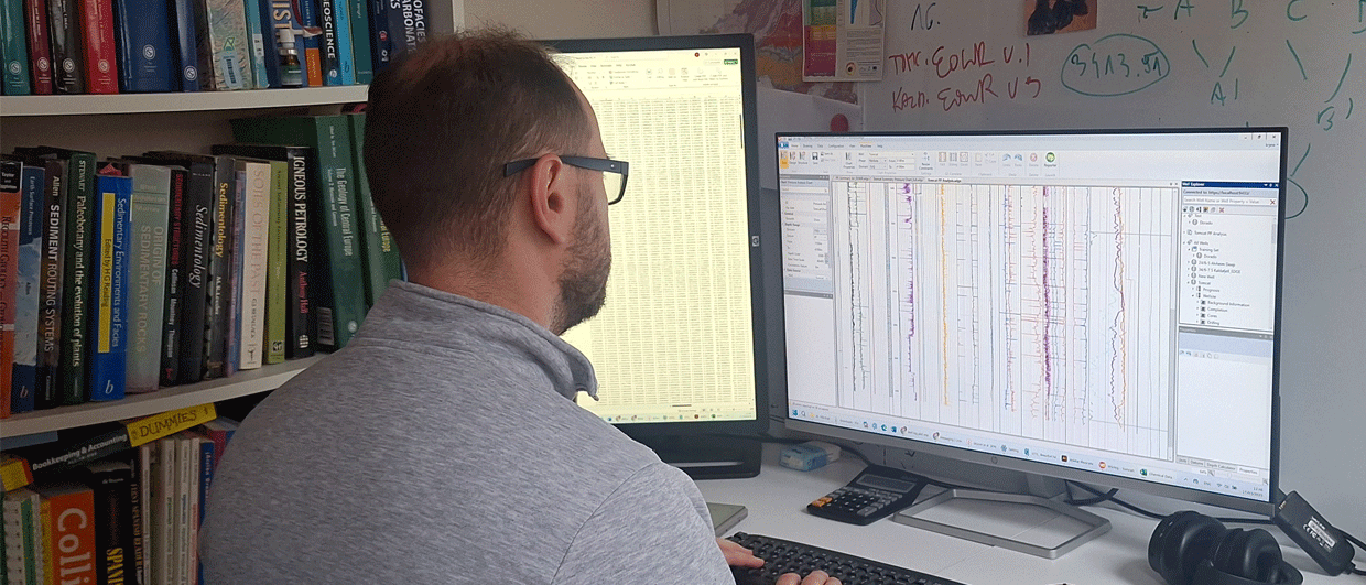
For these reasons, data to support setting casing prior to entering the reservoir is of key importance. The need for additional data is augmented by the fact that in case of Shearwater, production wells were drilled in a liner (DIL) which excluded the use of LWD tools as part of the drill string. This caused a potential increase in stratigraphic uncertainty, which had to be compensated through the use of a different set of tools. Geochemical characterisation of cutting samples in one of those tools, as well as deriving a synthetic GR curve on the basis of the geochemical analysis results.
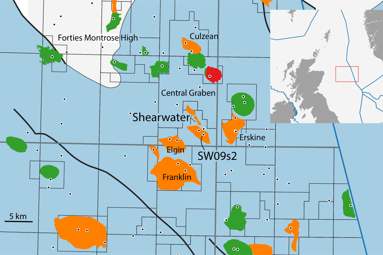
The Shearwater field in situated in Block 22/30b in the UK Central North Sea and is part of a cluster of HPHT fields such as Elgin, Franklin, Erskine and Culzean. Gas and condensate are produced from the Upper Jurassic Fulmar formation since the year 2000. Virgin pressure at the crest of the structure was in excess of 15,000 psi. The subsequent reduction in reservoir pressure led to compaction and mechanical failure of all original development wells. At the time of field sanction, it was thought to be impossible to drill further infill wells due to the closure of the already narrow drilling window. However, new drilling techniques have since been developed, amongst which the drilling in liner (DIL) technique.
The direct overburden of the Shearwater Upper Jurassic Fulmar reservoir consists of the Heather, Kimmeridge Clay and Vallhall formations and the Chalk Group. A chemostratigraphic scheme was therefore established to effectively differentiaate between these units. The Chalk is characterised by high CaO values, with individual Chalk formations such as the Hidra, Herring and Hod displaying consistent variations in Si and Al ratios.
The mudstones of the Kimmeridge Clay exhibit relatively high uranium (U) concentrations, which enables differentiation from the Vallhall and Heather formations. In turn, the latter two could be differentiated through CaO content, with the Vallhall showing elevated levels.

Drilling of production well SW09s2
First of all, the total depth (TD) of the conventional 61/2” bottom hole assembly had to be placed as close to the base of the Vallhall formation as possible, thereby minimising the length of the 61/2” DIL section and maximising the chance of reaching the Fulmar reservoir. Nb/Y and Y/Th ratios aided in identifying the expected Vallhall zonation, which together with biostratigraphy resulted in a TD of the 61/2” conventional section at a depth of 16,635 ft.
Although cutting sample quality in the subsequent DIL section was very poor, thanks to a slow ROP and an adapted sample preparation technique, synthetic GR profiles could be established. This allowed identification of the top Kimmeridge Clay at a depth of 16,715 ft and the subsequent transition into the Heather Formation.
The top Fulmar turned out to be very difficult to determine, as the drilling mud was dominated by Lost Circulation Material (LCM), which is used to block open fractures and pores of permeable strata. Also, caved organic-rich shales were frequently found the uppermost Fulmar section. In addition, visual inspection of the rock flour representing the true formation did not conclusively lead to a Fulmar sandstone interpretation. It was only through the geochemical composition that a sandstone origin could be further supported.
Despite these challenges, the DIL section TD could be called at 16,863 ft, about 110 ft into the reservoir. The remaining section was safely drilled with the 41/2” section.
This article is based on a paper that was published earlier this year by a team from RPS and Shell. Please see the full reference below.
HENK KOMBRINK
Daniel Atkin, Manuel Vieira & Ben Taylor, 2020. Applications of real-time chemical stratigraphy in support of the safe drilling of HPHT wells: examples from the Shearwater Field, Central North Sea, UK. Petroleum Geoscience, http://dx.doi.org/10.1144/petgeo2019-081.